Netgear GS724Tv4 Software Administration Manual - Page 99
STP Configuration, To con STP settings on the switch, Switching, Basic, Configuration Name
 |
View all Netgear GS724Tv4 manuals
Add to My Manuals
Save this manual to your list of manuals |
Page 99 highlights
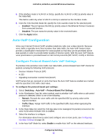
GS716Tv3, GS724Tv4, and GS748Tv5 Smart Switches STP Configuration The STP Configuration screen contains fields for enabling STP on the switch. To configure STP settings on the switch: 1. Select Switching > STP > Basic > STP Configuration. 2. Next to Spanning Tree State, specify whether to enable or disable Spanning Tree operation on the switch. 3. From the STP Operation Mode field, specify the Force Protocol Version parameter for the switch. Options are: • STP (Spanning Tree Protocol). IEEE 802.1D • RSTP (Rapid Spanning Tree Protocol). IEEE 802.1w • MSTP (Multiple Spanning Tree Protocol). IEEE 802.1s 4. Specify the configuration name and revision level. • Configuration Name. Name used to identify the configuration currently being used. It can be up to 32 alphanumeric characters. • Configuration Revision Level. Number used to identify the configuration currently being used. The values allowed are between 0 and 65535. The default value is 0. 5. Next to Forward BPDU while STP Disabled, select Enable to allow spanning tree BPDUs to be forwarded while spanning-tree is disabled on the switch, or select Disable to prevent BPDUs from being forwarded when STP is disabled on the switch. 6. Click the Apply button. The following table describes the STP status information available on the screen. Table 23. STP status information Field Description Configuration Digest Key This is used to identify the configuration currently being used. Bridge Identifier The bridge identifier for the CST. It is made up using the bridge priority and the base MAC address of the bridge. Time Since Topology Change The time in seconds since the topology of the CST last changed. Topology Change Count The number of times the topology has changed for the CST. Topology Change The value of the topology change parameter for the switch indicating if a topology change is in progress on any port assigned to the CST. The value is either True or False. Designated Root The bridge identifier of the root bridge. It is made up from the bridge priority and the base MAC address of the bridge. Root Path Cost Path cost to the Designated Root for the CST. Root Port Port to access the Designated Root for the CST. Configuring Switching 99
-
 1
1 -
2
-
3
-
4
-
5
-
6
-
7
-
8
-
9
-
10
-
11
-
12
-
13
-
14
-
15
-
16
-
17
-
18
-
19
-
20
-
21
-
22
-
23
-
24
-
25
-
26
-
27
-
28
-
29
-
30
-
31
-
32
-
33
-
34
-
35
-
36
-
37
-
38
-
39
-
40
-
41
-
42
-
43
-
44
-
45
-
46
-
47
-
48
-
49
-
50
-
51
-
52
-
53
-
54
-
55
-
56
-
57
-
58
-
59
-
60
-
61
-
62
-
63
-
64
-
65
-
66
-
67
-
68
-
69
-
70
-
71
-
72
-
73
-
74
-
75
-
76
-
77
-
78
-
79
-
80
-
81
-
82
-
83
-
84
-
85
-
86
-
87
-
88
-
89
-
90
-
91
-
92
-
93
-
 94
94 -
 95
95 -
 96
96 -
 97
97 -
 98
98 -
 99
99 -
 100
100 -
 101
101 -
 102
102 -
 103
103 -
 104
104 -
105
-
106
-
107
-
108
-
109
-
110
-
111
-
112
-
113
-
114
-
115
-
116
-
117
-
118
-
119
-
120
-
121
-
122
-
123
-
124
-
125
-
126
-
127
-
128
-
129
-
130
-
131
-
132
-
133
-
134
-
135
-
136
-
137
-
138
-
139
-
140
-
141
-
142
-
143
-
144
-
145
-
146
-
147
-
148
-
149
-
150
-
151
-
152
-
153
-
154
-
155
-
156
-
157
-
158
-
159
-
160
-
161
-
162
-
163
-
164
-
165
-
166
-
167
-
168
-
169
-
170
-
171
-
172
-
173
-
174
-
175
-
176
-
177
-
178
-
179
-
180
-
181
-
182
-
183
-
184
-
185
-
186
-
187
-
188
-
189
-
190
-
191
-
192
-
193
-
194
-
195
-
196
-
197
-
198
-
199
-
200
-
201
-
202
-
203
-
204
-
205
-
206
-
207
-
208
-
209
-
210
-
211
-
212
-
213
-
214
-
215
-
216
-
217
-
218
-
219
-
220
-
221
-
222
-
223
-
224
-
225
-
226
-
227
-
228
-
229
-
230
-
231
-
232
-
233
-
234
-
235
-
236
-
237
-
238
-
239
-
240
-
241
-
242
-
243
-
244
-
245
-
246
-
247
-
248
-
249
-
250
-
251
-
252
-
253
-
254
-
255
-
256
-
257
-
258
-
259
-
260
-
261
-
262
-
263
-
264
-
265
-
266
-
267
-
268
-
269
-
270
-
271
-
272
-
273
-
274
-
275
-
276
-
277
-
278
-
279
-
280
-
281
-
282
-
283
-
284
-
285
-
286
-
287
-
288
-
289
-
290
 |
 |