Dell PowerEdge 2321DS User Manual - Page 53
Controlling Your System at the Analog Ports, Viewing and Selecting Ports and Devices
 |
View all Dell PowerEdge 2321DS manuals
Add to My Manuals
Save this manual to your list of manuals |
Page 53 highlights
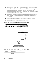
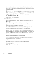
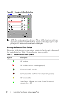
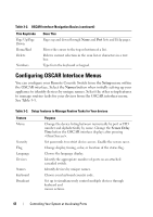
3 Controlling Your System at the Analog Ports The Remote Console Switch features user-side keyboard and mouse ports that allow you to connect a USB or PS/2 keyboard and mouse for direct analog access. The Remote Console Switch uses the powerful OSCAR interface, which uses intuitive menus to configure your system and select computers. Viewing and Selecting Ports and Devices Use the OSCAR Main dialog box to view, configure, and control devices in the Remote Console Switch system. View your devices by name, port, or by the unique Electronic ID number (EID) embedded in each SIP module. The Port column indicates the ARI port to which a device is connected. If you cascade a switch from the main Remote Console Switch, creating another tier, the port numbering displays the ARI port first, then the switch port to which the device is connected. For example, in Figure 3-1, devices 06-01, 0602, 06-03, and 06-04 are connected to switches. The port numbering displays the ARI port first, then the switch port to which the device is connected. If you cascade a switch from a Port Expansion Module (PEM), you will also see multiple devices that show up on a single port. To access the Main dialog box: Press to launch the OSCAR interface. The Main dialog box displays. Controlling Your System at the Analog Ports 36
-
 1
1 -
2
-
3
-
4
-
5
-
6
-
7
-
8
-
9
-
10
-
11
-
12
-
13
-
14
-
15
-
16
-
17
-
18
-
19
-
20
-
21
-
22
-
23
-
24
-
25
-
26
-
27
-
28
-
29
-
30
-
31
-
32
-
33
-
34
-
35
-
36
-
37
-
38
-
39
-
40
-
41
-
42
-
43
-
44
-
45
-
46
-
47
-
 48
48 -
 49
49 -
 50
50 -
 51
51 -
 52
52 -
 53
53 -
 54
54 -
 55
55 -
 56
56 -
 57
57 -
 58
58 -
59
-
60
-
61
-
62
-
63
-
64
-
65
-
66
-
67
-
68
-
69
-
70
-
71
-
72
-
73
-
74
-
75
-
76
-
77
-
78
-
79
-
80
-
81
-
82
-
83
-
84
-
85
-
86
-
87
-
88
-
89
-
90
-
91
-
92
-
93
-
94
-
95
-
96
-
97
-
98
-
99
-
100
-
101
-
102
-
103
-
104
-
105
-
106
-
107
-
108
-
109
-
110
-
111
-
112
-
113
-
114
-
115
-
116
-
117
-
118
-
119
-
120
-
121
-
122
-
123
-
124
-
125
-
126
-
127
-
128
-
129
-
130
-
131
-
132
-
133
-
134
-
135
-
136
-
137
-
138
-
139
-
140
-
141
-
142
-
143
-
144
-
145
-
146
-
147
-
148
-
149
-
150
-
151
-
152
-
153
-
154
-
155
-
156
-
157
-
158
-
159
-
160
-
161
-
162
-
163
-
164
-
165
-
166
-
167
-
168
-
169
-
170
-
171
-
172
-
173
-
174
-
175
-
176
-
177
-
178
-
179
-
180
-
181
-
182
-
183
-
184
-
185
-
186
-
187
-
188
-
189
-
190
-
191
-
192
-
193
-
194
-
195
-
196
-
197
-
198
-
199
-
200
-
201
-
202
-
203
-
204
-
205
-
206
-
207
-
208
-
209
-
210
-
211
-
212
-
213
-
214
-
215
-
216
-
217
-
218
-
219
-
220
-
221
-
222
-
223
-
224
-
225
-
226
-
227
-
228
-
229
-
230
-
231
-
232
-
233
-
234
-
235
-
236
-
237
-
238
-
239
-
240
-
241
-
242
-
243
-
244
-
245
-
246
-
247
-
248
-
249
-
250
-
251
-
252
-
253
-
254
-
255
-
256
-
257
-
258
-
259
-
260
-
261
-
262
-
263
-
264
-
265
-
266
-
267
-
268
-
269
-
270
-
271
-
272
-
273
-
274
-
275
-
276
-
277
-
278
-
279
-
280
 |
 |