D-Link DGS-3426P Product Manual - Page 155
GVRP Settings, GVRP Settings window
 |
UPC - 790069291982
View all D-Link DGS-3426P manuals
Add to My Manuals
Save this manual to your list of manuals |
Page 155 highlights
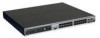
xStack® DGS-3400 Series Layer 2 Gigabit Ethernet Managed Switch GVRP Settings The GVRP Settings window allows the user to determine whether the Switch will share its VLAN configuration information with other GARP VLAN Registration Protocol (GVRP) enabled switches. In addition, Ingress Checking can be used to limit traffic by filtering incoming packets whose PVID does not match the PVID of the port. Results can be seen in the table under the configuration settings, as seen below. To view this window, click L2 Features > VLAN > GVRP Settings, as shown on the right: Figure 3 - 8 GVRP Settings window The following fields can be configured: Parameter Description Unit Select the switch in the switch stack to be modified. From / To These two fields allow the range of ports that will be included in the Port-based VLAN created using the 802.1Q Port Settings window, to be specified. GVRP The GARP VLAN Registration Protocol (GVRP) enables the port to dynamically become a member of a VLAN. GVRP is Disabled by default. Ingress Check This field can be toggled using the space bar between Enabled and Disabled. Enabled enables the port to compare the VID tag of an incoming packet with the PVID number assigned to the port. If the two are different, the port filters (drops) the packet. Disabled disables ingress filtering. Ingress Checking is Enabled by default. Acceptable Frame Type This field denotes the type of frame that will be accepted by the port. The user may choose between Tagged Only, which means only VLAN tagged frames will be accepted, and Admit_All, which mean both tagged and untagged frames will be accepted. Admit_All is enabled by default. PVID The read-only field in the 802.1Q Port Table shows the current PVID assignment for each port, which may be manually assigned to a VLAN when created in the 802.1Q Port Settings table. The Switch's default is to assign all ports to the default VLAN with a VID of 1.The PVID is used by the port to tag outgoing, untagged packets, and to make filtering decisions about incoming packets. If the port is specified to accept only tagged frames - as tagging, and an untagged packet is forwarded to the port for transmission, the port will add an 802.1Q tag using the PVID to write the VID in the tag. When the packet arrives at its destination, the receiving device will use the PVID to 146
-
 1
1 -
2
-
3
-
4
-
5
-
6
-
7
-
8
-
9
-
10
-
11
-
12
-
13
-
14
-
15
-
16
-
17
-
18
-
19
-
20
-
21
-
22
-
23
-
24
-
25
-
26
-
27
-
28
-
29
-
30
-
31
-
32
-
33
-
34
-
35
-
36
-
37
-
38
-
39
-
40
-
41
-
42
-
43
-
44
-
45
-
46
-
47
-
48
-
49
-
50
-
51
-
52
-
53
-
54
-
55
-
56
-
57
-
58
-
59
-
60
-
61
-
62
-
63
-
64
-
65
-
66
-
67
-
68
-
69
-
70
-
71
-
72
-
73
-
74
-
75
-
76
-
77
-
78
-
79
-
80
-
81
-
82
-
83
-
84
-
85
-
86
-
87
-
88
-
89
-
90
-
91
-
92
-
93
-
94
-
95
-
96
-
97
-
98
-
99
-
100
-
101
-
102
-
103
-
104
-
105
-
106
-
107
-
108
-
109
-
110
-
111
-
112
-
113
-
114
-
115
-
116
-
117
-
118
-
119
-
120
-
121
-
122
-
123
-
124
-
125
-
126
-
127
-
128
-
129
-
130
-
131
-
132
-
133
-
134
-
135
-
136
-
137
-
138
-
139
-
140
-
141
-
142
-
143
-
144
-
145
-
146
-
147
-
148
-
149
-
 150
150 -
 151
151 -
 152
152 -
 153
153 -
 154
154 -
 155
155 -
 156
156 -
 157
157 -
 158
158 -
 159
159 -
 160
160 -
161
-
162
-
163
-
164
-
165
-
166
-
167
-
168
-
169
-
170
-
171
-
172
-
173
-
174
-
175
-
176
-
177
-
178
-
179
-
180
-
181
-
182
-
183
-
184
-
185
-
186
-
187
-
188
-
189
-
190
-
191
-
192
-
193
-
194
-
195
-
196
-
197
-
198
-
199
-
200
-
201
-
202
-
203
-
204
-
205
-
206
-
207
-
208
-
209
-
210
-
211
-
212
-
213
-
214
-
215
-
216
-
217
-
218
-
219
-
220
-
221
-
222
-
223
-
224
-
225
-
226
-
227
-
228
-
229
-
230
-
231
-
232
-
233
-
234
-
235
-
236
-
237
-
238
-
239
-
240
-
241
-
242
-
243
-
244
-
245
-
246
-
247
-
248
-
249
-
250
-
251
-
252
-
253
-
254
-
255
-
256
-
257
-
258
-
259
-
260
-
261
-
262
-
263
-
264
-
265
-
266
-
267
-
268
-
269
-
270
-
271
-
272
-
273
-
274
-
275
-
276
-
277
-
278
-
279
-
280
-
281
-
282
-
283
-
284
-
285
-
286
-
287
-
288
-
289
-
290
-
291
-
292
-
293
-
294
-
295
-
296
-
297
-
298
-
299
-
300
-
301
-
302
-
303
-
304
-
305
-
306
-
307
-
308
-
309
-
310
-
311
-
312
-
313
-
314
-
315
-
316
-
317
-
318
-
319
-
320
-
321
-
322
-
323
-
324
-
325
-
326
-
327
-
328
-
329
-
330
-
331
-
332
-
333
-
334
-
335
-
336
-
337
-
338
-
339
-
340
-
341
-
342
-
343
-
344
-
345
-
346
-
347
-
348
-
349
-
350
-
351
-
352
-
353
-
354
-
355
-
356
-
357
-
358
-
359
-
360
-
361
-
362
-
363
-
364
-
365
-
366
-
367
-
368
-
369
-
370
-
371
-
372
-
373
-
374
-
375
-
376
-
377
-
378
-
379
-
380
-
381
-
382
-
383
-
384
-
385
-
386
-
387
-
388
-
389
-
390
-
391
-
392
-
393
-
394
-
395
-
396
-
397
-
398
-
399
-
400
-
401
-
402
-
403
-
404
-
405
-
406
-
407
-
408
-
409
-
410
-
411
-
412
-
413
-
414
-
415
-
416
-
417
-
418
-
419
-
420
-
421
-
422
-
423
-
424
 |
 |