D-Link DGS-3426P Product Manual - Page 30
Stacking, RA Managed Flag, RA Other Con RA Max Router, AdvInterval sec
 |
UPC - 790069291982
View all D-Link DGS-3426P manuals
Add to My Manuals
Save this manual to your list of manuals |
Page 30 highlights
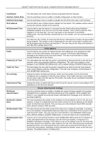
xStack® DGS-3400 Series Layer 2 Gigabit Ethernet Managed Switch RA Managed Flag RA Other Configure Flag RA Max Router AdvInterval (sec) RA Min Router AdvInterval (sec) Use the pull-down menu to enable or disable the Managed flag. When enabled, this will trigger the router to use a stateful autoconfiguration process to get both Global and linklocal IPv6 addresses for the Switch. The default setting is Disabled. Use the pull-down menu to enable or disable the Managed flag. When enabled, this will trigger the router to use a stateful autoconfiguration process to get configuration information that is not address information, yet is important to the IPv6 settings of the Switch. The default setting is Disabled. Used to set the maximum interval time between the dispatch of router advertisements by this interface over the link-local network. This entry must be no less than 4 seconds (4000 milliseconds) and no more than 1800 seconds. The user may configure a time between 4 and 1800 seconds with a default setting of 600 seconds. Used to set the minimum interval time between the dispatch of router advertisements by this interface over the link-local network. This entry must be no less then 3 seconds and no more than .75 (3/4) of the MaxRtrAdvInterval. The user may configure a time between 3 and 1350 seconds with a default setting of 198 seconds. Click Apply to implement the changes. Stacking From firmware release v2.00 of this Switch, the xStack® DGS-3400 series now supports switch stacking, where a set of twelve switches can be combined to be managed by one IP address through Telnet, the GUI interface (web), the console port or through SNMP. Each switch of this series has either two or three stacking slots located at the rear of the device, which can be used to add 10-gigabit DEM-410CX or DEM-410X stacking modules, sold separately. After adding these stacking ports, the user may connect these ports together using copper or fiber stacking cables (also sold separately) in one of two possible topologies. Duplex Ring - As shown in Figure 2-9, the Duplex Ring stacks switches in a ring or circle format where data can be transferred in two directions. This topology is very resilient because if there is a break in the ring, data can still be transferred through the stacking cables between switches in the stack. Duplex Chain - As shown in Figure 2-10, The Duplex Chain topology stacks switches together in a chain-link format. Using this method, data transfer is only possible in one direction and if there is a break in the chain, then data transfer will obviously be affected. 21
-
 1
1 -
2
-
3
-
4
-
5
-
6
-
7
-
8
-
9
-
10
-
11
-
12
-
13
-
14
-
15
-
16
-
17
-
18
-
19
-
20
-
21
-
22
-
23
-
24
-
 25
25 -
 26
26 -
 27
27 -
 28
28 -
 29
29 -
 30
30 -
 31
31 -
 32
32 -
 33
33 -
 34
34 -
 35
35 -
36
-
37
-
38
-
39
-
40
-
41
-
42
-
43
-
44
-
45
-
46
-
47
-
48
-
49
-
50
-
51
-
52
-
53
-
54
-
55
-
56
-
57
-
58
-
59
-
60
-
61
-
62
-
63
-
64
-
65
-
66
-
67
-
68
-
69
-
70
-
71
-
72
-
73
-
74
-
75
-
76
-
77
-
78
-
79
-
80
-
81
-
82
-
83
-
84
-
85
-
86
-
87
-
88
-
89
-
90
-
91
-
92
-
93
-
94
-
95
-
96
-
97
-
98
-
99
-
100
-
101
-
102
-
103
-
104
-
105
-
106
-
107
-
108
-
109
-
110
-
111
-
112
-
113
-
114
-
115
-
116
-
117
-
118
-
119
-
120
-
121
-
122
-
123
-
124
-
125
-
126
-
127
-
128
-
129
-
130
-
131
-
132
-
133
-
134
-
135
-
136
-
137
-
138
-
139
-
140
-
141
-
142
-
143
-
144
-
145
-
146
-
147
-
148
-
149
-
150
-
151
-
152
-
153
-
154
-
155
-
156
-
157
-
158
-
159
-
160
-
161
-
162
-
163
-
164
-
165
-
166
-
167
-
168
-
169
-
170
-
171
-
172
-
173
-
174
-
175
-
176
-
177
-
178
-
179
-
180
-
181
-
182
-
183
-
184
-
185
-
186
-
187
-
188
-
189
-
190
-
191
-
192
-
193
-
194
-
195
-
196
-
197
-
198
-
199
-
200
-
201
-
202
-
203
-
204
-
205
-
206
-
207
-
208
-
209
-
210
-
211
-
212
-
213
-
214
-
215
-
216
-
217
-
218
-
219
-
220
-
221
-
222
-
223
-
224
-
225
-
226
-
227
-
228
-
229
-
230
-
231
-
232
-
233
-
234
-
235
-
236
-
237
-
238
-
239
-
240
-
241
-
242
-
243
-
244
-
245
-
246
-
247
-
248
-
249
-
250
-
251
-
252
-
253
-
254
-
255
-
256
-
257
-
258
-
259
-
260
-
261
-
262
-
263
-
264
-
265
-
266
-
267
-
268
-
269
-
270
-
271
-
272
-
273
-
274
-
275
-
276
-
277
-
278
-
279
-
280
-
281
-
282
-
283
-
284
-
285
-
286
-
287
-
288
-
289
-
290
-
291
-
292
-
293
-
294
-
295
-
296
-
297
-
298
-
299
-
300
-
301
-
302
-
303
-
304
-
305
-
306
-
307
-
308
-
309
-
310
-
311
-
312
-
313
-
314
-
315
-
316
-
317
-
318
-
319
-
320
-
321
-
322
-
323
-
324
-
325
-
326
-
327
-
328
-
329
-
330
-
331
-
332
-
333
-
334
-
335
-
336
-
337
-
338
-
339
-
340
-
341
-
342
-
343
-
344
-
345
-
346
-
347
-
348
-
349
-
350
-
351
-
352
-
353
-
354
-
355
-
356
-
357
-
358
-
359
-
360
-
361
-
362
-
363
-
364
-
365
-
366
-
367
-
368
-
369
-
370
-
371
-
372
-
373
-
374
-
375
-
376
-
377
-
378
-
379
-
380
-
381
-
382
-
383
-
384
-
385
-
386
-
387
-
388
-
389
-
390
-
391
-
392
-
393
-
394
-
395
-
396
-
397
-
398
-
399
-
400
-
401
-
402
-
403
-
404
-
405
-
406
-
407
-
408
-
409
-
410
-
411
-
412
-
413
-
414
-
415
-
416
-
417
-
418
-
419
-
420
-
421
-
422
-
423
-
424
 |
 |