D-Link DGS-3426P Product Manual - Page 248
Access Profile Entry Display window IP, Apply, Access Profile Table
 |
UPC - 790069291982
View all D-Link DGS-3426P manuals
Add to My Manuals
Save this manual to your list of manuals |
Page 248 highlights
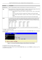
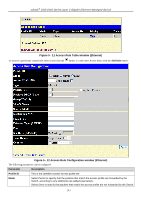
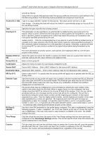
xStack® DGS-3400 Series Layer 2 Gigabit Ethernet Managed Switch • Type - Further specify that the access profile will apply an ICMP type value. • Code - Further specify that the access profile will apply an ICMP code value. Select IGMP to instruct the Switch to examine the Internet Group Management Protocol (IGMP) field in each frame's header. • Type - Further specify that the access profile will apply an IGMP type value. Select TCP to use the TCP port number contained in an incoming packet as the forwarding criterion. Selecting TCP requires that you specify a source port mask and/or a destination port mask. • src port mask - Specify a TCP port mask for the source port in hex form (hex 0x0- 0xffff), which you wish to filter. • dst port mask - Specify a TCP port mask for the destination port in hex form (hex 0x0-0xffff) which you wish to filter. • flag bit - The user may also identify which flag bits to filter. Flag bits are parts of a packet that determine what to do with the packet. The user may filter packets by filtering certain flag bits within the packets, by checking the boxes corresponding to the flag bits of the TCP field. The user may choose between urg (urgent), ack (acknowledgement), psh (push), rst (reset), syn (synchronize), fin (finish). Select UDP to use the UDP port number contained in an incoming packet as the forwarding criterion. Selecting UDP requires that you specify a source port mask and/or a destination port mask. • src port mask - Specify a UDP port mask for the source port in hex form (hex 0x00xffff). • dst port mask - Specify a UDP port mask for the destination port in hex form (hex 0x0-0xffff). protocol id - Enter a value defining the protocol ID in the packet header to mask. Specify the protocol ID mask in hex form (hex 0x0-0xff). Click Apply to implement the changes. To view the settings for a created profile, click its corresponding View button in the Access Profile Table window, revealing the following window. Figure 5 - 6 Access Profile Entry Display window (IP) The page shown below is the IPv6 configuration window. 239
-
 1
1 -
2
-
3
-
4
-
5
-
6
-
7
-
8
-
9
-
10
-
11
-
12
-
13
-
14
-
15
-
16
-
17
-
18
-
19
-
20
-
21
-
22
-
23
-
24
-
25
-
26
-
27
-
28
-
29
-
30
-
31
-
32
-
33
-
34
-
35
-
36
-
37
-
38
-
39
-
40
-
41
-
42
-
43
-
44
-
45
-
46
-
47
-
48
-
49
-
50
-
51
-
52
-
53
-
54
-
55
-
56
-
57
-
58
-
59
-
60
-
61
-
62
-
63
-
64
-
65
-
66
-
67
-
68
-
69
-
70
-
71
-
72
-
73
-
74
-
75
-
76
-
77
-
78
-
79
-
80
-
81
-
82
-
83
-
84
-
85
-
86
-
87
-
88
-
89
-
90
-
91
-
92
-
93
-
94
-
95
-
96
-
97
-
98
-
99
-
100
-
101
-
102
-
103
-
104
-
105
-
106
-
107
-
108
-
109
-
110
-
111
-
112
-
113
-
114
-
115
-
116
-
117
-
118
-
119
-
120
-
121
-
122
-
123
-
124
-
125
-
126
-
127
-
128
-
129
-
130
-
131
-
132
-
133
-
134
-
135
-
136
-
137
-
138
-
139
-
140
-
141
-
142
-
143
-
144
-
145
-
146
-
147
-
148
-
149
-
150
-
151
-
152
-
153
-
154
-
155
-
156
-
157
-
158
-
159
-
160
-
161
-
162
-
163
-
164
-
165
-
166
-
167
-
168
-
169
-
170
-
171
-
172
-
173
-
174
-
175
-
176
-
177
-
178
-
179
-
180
-
181
-
182
-
183
-
184
-
185
-
186
-
187
-
188
-
189
-
190
-
191
-
192
-
193
-
194
-
195
-
196
-
197
-
198
-
199
-
200
-
201
-
202
-
203
-
204
-
205
-
206
-
207
-
208
-
209
-
210
-
211
-
212
-
213
-
214
-
215
-
216
-
217
-
218
-
219
-
220
-
221
-
222
-
223
-
224
-
225
-
226
-
227
-
228
-
229
-
230
-
231
-
232
-
233
-
234
-
235
-
236
-
237
-
238
-
239
-
240
-
241
-
242
-
 243
243 -
 244
244 -
 245
245 -
 246
246 -
 247
247 -
 248
248 -
 249
249 -
 250
250 -
 251
251 -
 252
252 -
 253
253 -
254
-
255
-
256
-
257
-
258
-
259
-
260
-
261
-
262
-
263
-
264
-
265
-
266
-
267
-
268
-
269
-
270
-
271
-
272
-
273
-
274
-
275
-
276
-
277
-
278
-
279
-
280
-
281
-
282
-
283
-
284
-
285
-
286
-
287
-
288
-
289
-
290
-
291
-
292
-
293
-
294
-
295
-
296
-
297
-
298
-
299
-
300
-
301
-
302
-
303
-
304
-
305
-
306
-
307
-
308
-
309
-
310
-
311
-
312
-
313
-
314
-
315
-
316
-
317
-
318
-
319
-
320
-
321
-
322
-
323
-
324
-
325
-
326
-
327
-
328
-
329
-
330
-
331
-
332
-
333
-
334
-
335
-
336
-
337
-
338
-
339
-
340
-
341
-
342
-
343
-
344
-
345
-
346
-
347
-
348
-
349
-
350
-
351
-
352
-
353
-
354
-
355
-
356
-
357
-
358
-
359
-
360
-
361
-
362
-
363
-
364
-
365
-
366
-
367
-
368
-
369
-
370
-
371
-
372
-
373
-
374
-
375
-
376
-
377
-
378
-
379
-
380
-
381
-
382
-
383
-
384
-
385
-
386
-
387
-
388
-
389
-
390
-
391
-
392
-
393
-
394
-
395
-
396
-
397
-
398
-
399
-
400
-
401
-
402
-
403
-
404
-
405
-
406
-
407
-
408
-
409
-
410
-
411
-
412
-
413
-
414
-
415
-
416
-
417
-
418
-
419
-
420
-
421
-
422
-
423
-
424
 |
 |
