D-Link DGS-3426P Product Manual - Page 249
Access Profile Configuration window IPv6, Parameter, Description, Profile ID 1-6, Class
 |
UPC - 790069291982
View all D-Link DGS-3426P manuals
Add to My Manuals
Save this manual to your list of manuals |
Page 249 highlights
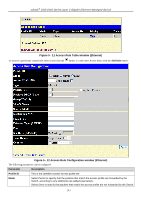
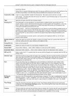
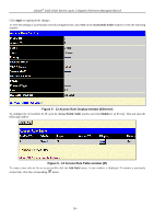
xStack® DGS-3400 Series Layer 2 Gigabit Ethernet Managed Switch Figure 5 - 7 Access Profile Configuration window (IPv6) The following parameters can be set, for IP: Parameter Description Profile ID (1-6) Type in a unique identifier number for this profile set. This value can be set from 1 to 6. Type Select profile based on Ethernet (MAC Address), IP, Packet Content or IPv6 address. This will change the menu according to the requirements for the type of profile. Select Ethernet to instruct the Switch to examine the layer 2 part of each packet header. Select IP to instruct the Switch to examine the IP address in each frame's header. Select IPv6 to instruct the Switch to examine the IPv6 address in each frame's header. Select Packet Content to instruct the Switch to examine the packet header. Class Checking this field will instruct the Switch to examine the class field of the IPv6 header. This class field is a part of the packet header that is similar to the Type of Service (ToS) or Precedence bits field in IPv4. Flow Label Checking this field will instruct the Switch to examine the flow label field of the IPv6 header. This flow label field is used by a source to label sequences of packets such as non-default quality of service or real time service packets. Source IPv6 Mask The user may specify an IP address mask for the source IPv6 address by checking the corresponding box and entering the IP address mask. Destination IPv6 Mask Protocol The user may specify an IP address mask for the destination IPv6 address by checking the corresponding box and entering the IP address mask. Selecting this option instructs the Switch to examine the protocol type value in each frame's header. Then the user must specify what protocol(s) to include according to the following guidelines: Select TCP to use the TCP port number contained in an incoming packet as the forwarding criterion. Selecting TCP requires that you specify a source port mask and/or a destination port mask. • src port mask - Specify a TCP port mask for the source port in hex form (hex 0x00xffff), which you wish to filter. • dst port mask - Specify a TCP port mask for the destination port in hex form (hex 240
-
 1
1 -
2
-
3
-
4
-
5
-
6
-
7
-
8
-
9
-
10
-
11
-
12
-
13
-
14
-
15
-
16
-
17
-
18
-
19
-
20
-
21
-
22
-
23
-
24
-
25
-
26
-
27
-
28
-
29
-
30
-
31
-
32
-
33
-
34
-
35
-
36
-
37
-
38
-
39
-
40
-
41
-
42
-
43
-
44
-
45
-
46
-
47
-
48
-
49
-
50
-
51
-
52
-
53
-
54
-
55
-
56
-
57
-
58
-
59
-
60
-
61
-
62
-
63
-
64
-
65
-
66
-
67
-
68
-
69
-
70
-
71
-
72
-
73
-
74
-
75
-
76
-
77
-
78
-
79
-
80
-
81
-
82
-
83
-
84
-
85
-
86
-
87
-
88
-
89
-
90
-
91
-
92
-
93
-
94
-
95
-
96
-
97
-
98
-
99
-
100
-
101
-
102
-
103
-
104
-
105
-
106
-
107
-
108
-
109
-
110
-
111
-
112
-
113
-
114
-
115
-
116
-
117
-
118
-
119
-
120
-
121
-
122
-
123
-
124
-
125
-
126
-
127
-
128
-
129
-
130
-
131
-
132
-
133
-
134
-
135
-
136
-
137
-
138
-
139
-
140
-
141
-
142
-
143
-
144
-
145
-
146
-
147
-
148
-
149
-
150
-
151
-
152
-
153
-
154
-
155
-
156
-
157
-
158
-
159
-
160
-
161
-
162
-
163
-
164
-
165
-
166
-
167
-
168
-
169
-
170
-
171
-
172
-
173
-
174
-
175
-
176
-
177
-
178
-
179
-
180
-
181
-
182
-
183
-
184
-
185
-
186
-
187
-
188
-
189
-
190
-
191
-
192
-
193
-
194
-
195
-
196
-
197
-
198
-
199
-
200
-
201
-
202
-
203
-
204
-
205
-
206
-
207
-
208
-
209
-
210
-
211
-
212
-
213
-
214
-
215
-
216
-
217
-
218
-
219
-
220
-
221
-
222
-
223
-
224
-
225
-
226
-
227
-
228
-
229
-
230
-
231
-
232
-
233
-
234
-
235
-
236
-
237
-
238
-
239
-
240
-
241
-
242
-
243
-
 244
244 -
 245
245 -
 246
246 -
 247
247 -
 248
248 -
 249
249 -
 250
250 -
 251
251 -
 252
252 -
 253
253 -
 254
254 -
255
-
256
-
257
-
258
-
259
-
260
-
261
-
262
-
263
-
264
-
265
-
266
-
267
-
268
-
269
-
270
-
271
-
272
-
273
-
274
-
275
-
276
-
277
-
278
-
279
-
280
-
281
-
282
-
283
-
284
-
285
-
286
-
287
-
288
-
289
-
290
-
291
-
292
-
293
-
294
-
295
-
296
-
297
-
298
-
299
-
300
-
301
-
302
-
303
-
304
-
305
-
306
-
307
-
308
-
309
-
310
-
311
-
312
-
313
-
314
-
315
-
316
-
317
-
318
-
319
-
320
-
321
-
322
-
323
-
324
-
325
-
326
-
327
-
328
-
329
-
330
-
331
-
332
-
333
-
334
-
335
-
336
-
337
-
338
-
339
-
340
-
341
-
342
-
343
-
344
-
345
-
346
-
347
-
348
-
349
-
350
-
351
-
352
-
353
-
354
-
355
-
356
-
357
-
358
-
359
-
360
-
361
-
362
-
363
-
364
-
365
-
366
-
367
-
368
-
369
-
370
-
371
-
372
-
373
-
374
-
375
-
376
-
377
-
378
-
379
-
380
-
381
-
382
-
383
-
384
-
385
-
386
-
387
-
388
-
389
-
390
-
391
-
392
-
393
-
394
-
395
-
396
-
397
-
398
-
399
-
400
-
401
-
402
-
403
-
404
-
405
-
406
-
407
-
408
-
409
-
410
-
411
-
412
-
413
-
414
-
415
-
416
-
417
-
418
-
419
-
420
-
421
-
422
-
423
-
424
 |
 |
