D-Link DGS-3426P Product Manual - Page 259
Flow Label, Source IPv6, Address, Destination IPv6, RX Rate 1, Time Range, Settings, Counter
 |
UPC - 790069291982
View all D-Link DGS-3426P manuals
Add to My Manuals
Save this manual to your list of manuals |
Page 259 highlights
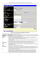
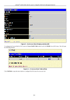
xStack® DGS-3400 Series Layer 2 Gigabit Ethernet Managed Switch Flow Label Source IPv6 Address Destination IPv6 Address Port RX Rate (1156249) Time Range header. This class field is a part of the packet header that is similar to the Type of Service (ToS) or Precedence bits field of IPv4. Configuring this field, in hex form, will instruct the Switch to examine the flow label field of the IPv6 header. This flow label field is used by a source to label sequences of packets such as nondefault quality of service or real time service packets. The user may specify an IP address mask for the source IPv6 address by entering the IP address mask, in hex form. The user may specify an IP address mask for the destination IPv6 address by and entering the IP address mask, in hex form. The Access Rule may be configured on a per-port basis by entering the port number of the switch in the switch stack into this field. When a range of ports is to be configured, the Auto Assign check box MUST be clicked in the Access ID field of this window. If not, the user will be presented with an error message and the access rule will not be configured. The port list is specified by listing the lowest switch number and the beginning port number on that switch, separated by a colon. Then the highest switch number and the highest port number of the range (also separated by a colon) are specified. The beginning and end of the port list range are separated by a dash. For example, 1:3 specifies switch number 1, port 3. 2:4 specifies switch number 2, port 4. 1:3 - 2:4 specifies all of the ports between switch 1, port 3 and switch 2, port 4 − in numerical order. Entering all will denote all ports on the Switch. Use this to limit RX bandwidth for the profile being configured. This rate is implemented using the following equation: 1 value = 64kbit/sec. (ex. If the user selects an RX rate of 10 then the ingress rate is 640kbit/sec.) The user many select a value between 1 and 156249, or No Limit. The default setting is No Limit. Click the check box and enter the name of the Time Range settings that has been previously configured in the Time Range Settings window. This will set specific times when this access rule will be implemented on the Switch. Counter Tick the check box and use the pull-down menu to employ the Counter that will count the packets identified with this rule. Users must note that if the Counter is employed in the ACL Flow Meter function, the Counter will automatically be disabled here, regardless of this setting. Click Apply to implement the changes. To view the settings of a previously correctly configured rule, click View in the Access Rule Table window to view the following window: 250
-
 1
1 -
2
-
3
-
4
-
5
-
6
-
7
-
8
-
9
-
10
-
11
-
12
-
13
-
14
-
15
-
16
-
17
-
18
-
19
-
20
-
21
-
22
-
23
-
24
-
25
-
26
-
27
-
28
-
29
-
30
-
31
-
32
-
33
-
34
-
35
-
36
-
37
-
38
-
39
-
40
-
41
-
42
-
43
-
44
-
45
-
46
-
47
-
48
-
49
-
50
-
51
-
52
-
53
-
54
-
55
-
56
-
57
-
58
-
59
-
60
-
61
-
62
-
63
-
64
-
65
-
66
-
67
-
68
-
69
-
70
-
71
-
72
-
73
-
74
-
75
-
76
-
77
-
78
-
79
-
80
-
81
-
82
-
83
-
84
-
85
-
86
-
87
-
88
-
89
-
90
-
91
-
92
-
93
-
94
-
95
-
96
-
97
-
98
-
99
-
100
-
101
-
102
-
103
-
104
-
105
-
106
-
107
-
108
-
109
-
110
-
111
-
112
-
113
-
114
-
115
-
116
-
117
-
118
-
119
-
120
-
121
-
122
-
123
-
124
-
125
-
126
-
127
-
128
-
129
-
130
-
131
-
132
-
133
-
134
-
135
-
136
-
137
-
138
-
139
-
140
-
141
-
142
-
143
-
144
-
145
-
146
-
147
-
148
-
149
-
150
-
151
-
152
-
153
-
154
-
155
-
156
-
157
-
158
-
159
-
160
-
161
-
162
-
163
-
164
-
165
-
166
-
167
-
168
-
169
-
170
-
171
-
172
-
173
-
174
-
175
-
176
-
177
-
178
-
179
-
180
-
181
-
182
-
183
-
184
-
185
-
186
-
187
-
188
-
189
-
190
-
191
-
192
-
193
-
194
-
195
-
196
-
197
-
198
-
199
-
200
-
201
-
202
-
203
-
204
-
205
-
206
-
207
-
208
-
209
-
210
-
211
-
212
-
213
-
214
-
215
-
216
-
217
-
218
-
219
-
220
-
221
-
222
-
223
-
224
-
225
-
226
-
227
-
228
-
229
-
230
-
231
-
232
-
233
-
234
-
235
-
236
-
237
-
238
-
239
-
240
-
241
-
242
-
243
-
244
-
245
-
246
-
247
-
248
-
249
-
250
-
251
-
252
-
253
-
 254
254 -
 255
255 -
 256
256 -
 257
257 -
 258
258 -
 259
259 -
 260
260 -
 261
261 -
 262
262 -
 263
263 -
 264
264 -
265
-
266
-
267
-
268
-
269
-
270
-
271
-
272
-
273
-
274
-
275
-
276
-
277
-
278
-
279
-
280
-
281
-
282
-
283
-
284
-
285
-
286
-
287
-
288
-
289
-
290
-
291
-
292
-
293
-
294
-
295
-
296
-
297
-
298
-
299
-
300
-
301
-
302
-
303
-
304
-
305
-
306
-
307
-
308
-
309
-
310
-
311
-
312
-
313
-
314
-
315
-
316
-
317
-
318
-
319
-
320
-
321
-
322
-
323
-
324
-
325
-
326
-
327
-
328
-
329
-
330
-
331
-
332
-
333
-
334
-
335
-
336
-
337
-
338
-
339
-
340
-
341
-
342
-
343
-
344
-
345
-
346
-
347
-
348
-
349
-
350
-
351
-
352
-
353
-
354
-
355
-
356
-
357
-
358
-
359
-
360
-
361
-
362
-
363
-
364
-
365
-
366
-
367
-
368
-
369
-
370
-
371
-
372
-
373
-
374
-
375
-
376
-
377
-
378
-
379
-
380
-
381
-
382
-
383
-
384
-
385
-
386
-
387
-
388
-
389
-
390
-
391
-
392
-
393
-
394
-
395
-
396
-
397
-
398
-
399
-
400
-
401
-
402
-
403
-
404
-
405
-
406
-
407
-
408
-
409
-
410
-
411
-
412
-
413
-
414
-
415
-
416
-
417
-
418
-
419
-
420
-
421
-
422
-
423
-
424
 |
 |
