D-Link DGS-3426P Product Manual - Page 56
Config Firmware Image, Config Firmware Image window
 |
UPC - 790069291982
View all D-Link DGS-3426P manuals
Add to My Manuals
Save this manual to your list of manuals |
Page 56 highlights
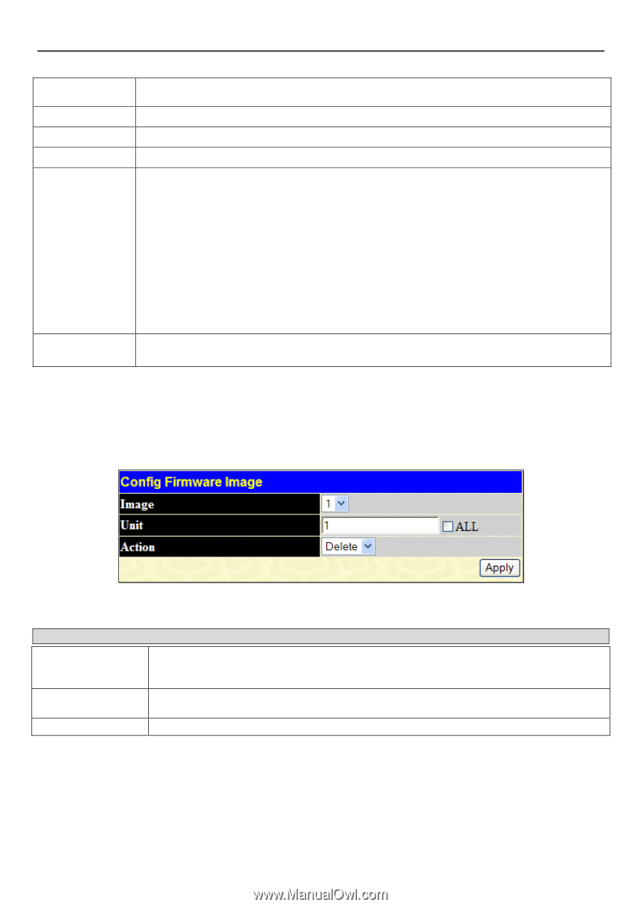
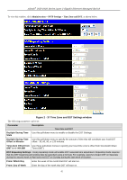
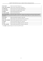
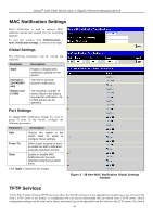
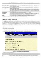
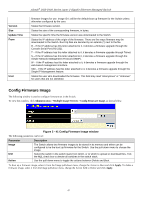
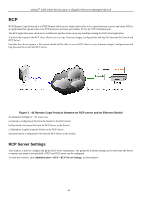
xStack® DGS-3400 Series Layer 2 Gigabit Ethernet Managed Switch Version Size Update Time From User firmware images for use. Image ID 1 will be the default boot up firmware for the Switch unless otherwise configured by the user. States the firmware version. States the size of the corresponding firmware, in bytes. States the specific time the firmware version was downloaded to the Switch. States the IP address of the origin of the firmware. There are five ways firmware may be downloaded to the Switch. Boot Up files are denoted by an asterisk (*) next to the file. R - If the IP address has this letter attached to it, it denotes a firmware upgrade through the Console Serial Port (RS-232). T - If the IP address has this letter attached to it, it denotes a firmware upgrade through Telnet. S - If the IP address has this letter attached to it, it denotes a firmware upgrade through the Simple Network Management Protocol (SNMP). W - If the IP address has this letter attached to it, it denotes a firmware upgrade through the web-based management interface. SIM - If the IP address has this letter attached to it, it denotes a firmware upgrade through the Single IP Management feature. States the user who downloaded the firmware. This field may read "Anonymous" or "Unknown" for users that are not identified. Config Firmware Image The following window is used to configure firmware set in the Switch. To view this window, click Administration > Multiple Image Services > Config Firmware Image, as shown below. Figure 2 - 41 Config Firmware Image window The following parameters can be set: Parameter Image Unit Action Description The Switch allows two firmware images to be stored in its memory and either can be configured to be the boot up firmware for the Switch. Use the pull-down menu to choose the image. Select the switch in the switch stack from which, or to which to upload or download files. Tick the ALL check box to denote all switches in the switch stack. Use the pull-down menu to toggle the actions between Delete and Boot. To boot up a firmware image, select it from the Image pull-down menu, change the Action to Boot and click Apply. To delete a firmware image, select it from the Image pull-down menu, change the Action field to Delete and click Apply. 47
-
 1
1 -
2
-
3
-
4
-
5
-
6
-
7
-
8
-
9
-
10
-
11
-
12
-
13
-
14
-
15
-
16
-
17
-
18
-
19
-
20
-
21
-
22
-
23
-
24
-
25
-
26
-
27
-
28
-
29
-
30
-
31
-
32
-
33
-
34
-
35
-
36
-
37
-
38
-
39
-
40
-
41
-
42
-
43
-
44
-
45
-
46
-
47
-
48
-
49
-
50
-
 51
51 -
 52
52 -
 53
53 -
 54
54 -
 55
55 -
 56
56 -
 57
57 -
 58
58 -
 59
59 -
 60
60 -
 61
61 -
62
-
63
-
64
-
65
-
66
-
67
-
68
-
69
-
70
-
71
-
72
-
73
-
74
-
75
-
76
-
77
-
78
-
79
-
80
-
81
-
82
-
83
-
84
-
85
-
86
-
87
-
88
-
89
-
90
-
91
-
92
-
93
-
94
-
95
-
96
-
97
-
98
-
99
-
100
-
101
-
102
-
103
-
104
-
105
-
106
-
107
-
108
-
109
-
110
-
111
-
112
-
113
-
114
-
115
-
116
-
117
-
118
-
119
-
120
-
121
-
122
-
123
-
124
-
125
-
126
-
127
-
128
-
129
-
130
-
131
-
132
-
133
-
134
-
135
-
136
-
137
-
138
-
139
-
140
-
141
-
142
-
143
-
144
-
145
-
146
-
147
-
148
-
149
-
150
-
151
-
152
-
153
-
154
-
155
-
156
-
157
-
158
-
159
-
160
-
161
-
162
-
163
-
164
-
165
-
166
-
167
-
168
-
169
-
170
-
171
-
172
-
173
-
174
-
175
-
176
-
177
-
178
-
179
-
180
-
181
-
182
-
183
-
184
-
185
-
186
-
187
-
188
-
189
-
190
-
191
-
192
-
193
-
194
-
195
-
196
-
197
-
198
-
199
-
200
-
201
-
202
-
203
-
204
-
205
-
206
-
207
-
208
-
209
-
210
-
211
-
212
-
213
-
214
-
215
-
216
-
217
-
218
-
219
-
220
-
221
-
222
-
223
-
224
-
225
-
226
-
227
-
228
-
229
-
230
-
231
-
232
-
233
-
234
-
235
-
236
-
237
-
238
-
239
-
240
-
241
-
242
-
243
-
244
-
245
-
246
-
247
-
248
-
249
-
250
-
251
-
252
-
253
-
254
-
255
-
256
-
257
-
258
-
259
-
260
-
261
-
262
-
263
-
264
-
265
-
266
-
267
-
268
-
269
-
270
-
271
-
272
-
273
-
274
-
275
-
276
-
277
-
278
-
279
-
280
-
281
-
282
-
283
-
284
-
285
-
286
-
287
-
288
-
289
-
290
-
291
-
292
-
293
-
294
-
295
-
296
-
297
-
298
-
299
-
300
-
301
-
302
-
303
-
304
-
305
-
306
-
307
-
308
-
309
-
310
-
311
-
312
-
313
-
314
-
315
-
316
-
317
-
318
-
319
-
320
-
321
-
322
-
323
-
324
-
325
-
326
-
327
-
328
-
329
-
330
-
331
-
332
-
333
-
334
-
335
-
336
-
337
-
338
-
339
-
340
-
341
-
342
-
343
-
344
-
345
-
346
-
347
-
348
-
349
-
350
-
351
-
352
-
353
-
354
-
355
-
356
-
357
-
358
-
359
-
360
-
361
-
362
-
363
-
364
-
365
-
366
-
367
-
368
-
369
-
370
-
371
-
372
-
373
-
374
-
375
-
376
-
377
-
378
-
379
-
380
-
381
-
382
-
383
-
384
-
385
-
386
-
387
-
388
-
389
-
390
-
391
-
392
-
393
-
394
-
395
-
396
-
397
-
398
-
399
-
400
-
401
-
402
-
403
-
404
-
405
-
406
-
407
-
408
-
409
-
410
-
411
-
412
-
413
-
414
-
415
-
416
-
417
-
418
-
419
-
420
-
421
-
422
-
423
-
424
 |
 |