D-Link DGS-3426P Product Manual - Page 47
System Log Save Mode Settings, System Log Save Mode Settings window
 |
UPC - 790069291982
View all D-Link DGS-3426P manuals
Add to My Manuals
Save this manual to your list of manuals |
Page 47 highlights
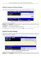
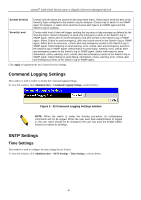
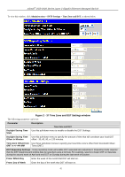
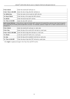
xStack® DGS-3400 Series Layer 2 Gigabit Ethernet Managed Switch Facility UDP Port (514 or 6000-65535) Status are Emergency, Alert, Critical, Error, Warning, Notice, Informational, Debug, All and Level. The default severity is Emergency. Some of the operating system daemons and processes have been assigned Facility values. Processes and daemons that have not been explicitly assigned a Facility may use any of the "local use" facilities or they may use the "user-level" Facility. Those Facilities that have been designated are shown in the following: Bold font means the facility values that the Switch currently now. Numerical Facility Numerical Facility Code Code 0 kernel messages 12 NTP subsystem 1 user-level messages 13 log audit 2 mail system 14 log alert 3 system daemons 15 clock daemon 4 security/authorization messages 16 local use 0 (local0) 5 messages generated internally by 17 local use 1 (local1) syslog line printer subsystem 18 local use 2 (local2) 7 network news subsystem 19 local use 3 (local3) 8 UUCP subsystem 20 local use 4 (local4) 9 clock daemon 21 local use 5 (local5) 10 security/authorization messages 22 local use 6 (local6) 11 FTP daemon 23 local use 7 (local7) Type the UDP port number used for sending Syslog messages. The default is 514. Choose Enabled or Disabled to activate or deactivate. To set the system log server configuration, click Apply. To return to the System Log Host window, click the Show All System Log Servers link. System Log Save Mode Settings This window may be used to choose a method for which to save the switch log to the flash memory on the Switch. To view this window, click Administration > System Log > System Log Save Mode Settings, as shown below. Figure 2 - 32 System Log Save Mode Settings window The following parameters can be configured: Parameter Description Save Mode Minute(s) Use the pull-down menu to choose the method for saving the switch log to the Flash memory. There are three options: Time Interval - Configure a time interval by which the switch will save the log files. On Demand - Only save log files when manually telling the Switch to do so. Go to Save Services > Save Changes to manually save log. On Trigger - Save log files to the Switch every time when a log event occurs on the Switch. When Time Interval is selected in Save Mode, set a time between 1 and 65535 minutes in the field. The default value is 1 minute. Click Apply to implement the changes. Click Save Log Now to immediately save log files currently on the Switch. 38
-
 1
1 -
2
-
3
-
4
-
5
-
6
-
7
-
8
-
9
-
10
-
11
-
12
-
13
-
14
-
15
-
16
-
17
-
18
-
19
-
20
-
21
-
22
-
23
-
24
-
25
-
26
-
27
-
28
-
29
-
30
-
31
-
32
-
33
-
34
-
35
-
36
-
37
-
38
-
39
-
40
-
41
-
 42
42 -
 43
43 -
 44
44 -
 45
45 -
 46
46 -
 47
47 -
 48
48 -
 49
49 -
 50
50 -
 51
51 -
 52
52 -
53
-
54
-
55
-
56
-
57
-
58
-
59
-
60
-
61
-
62
-
63
-
64
-
65
-
66
-
67
-
68
-
69
-
70
-
71
-
72
-
73
-
74
-
75
-
76
-
77
-
78
-
79
-
80
-
81
-
82
-
83
-
84
-
85
-
86
-
87
-
88
-
89
-
90
-
91
-
92
-
93
-
94
-
95
-
96
-
97
-
98
-
99
-
100
-
101
-
102
-
103
-
104
-
105
-
106
-
107
-
108
-
109
-
110
-
111
-
112
-
113
-
114
-
115
-
116
-
117
-
118
-
119
-
120
-
121
-
122
-
123
-
124
-
125
-
126
-
127
-
128
-
129
-
130
-
131
-
132
-
133
-
134
-
135
-
136
-
137
-
138
-
139
-
140
-
141
-
142
-
143
-
144
-
145
-
146
-
147
-
148
-
149
-
150
-
151
-
152
-
153
-
154
-
155
-
156
-
157
-
158
-
159
-
160
-
161
-
162
-
163
-
164
-
165
-
166
-
167
-
168
-
169
-
170
-
171
-
172
-
173
-
174
-
175
-
176
-
177
-
178
-
179
-
180
-
181
-
182
-
183
-
184
-
185
-
186
-
187
-
188
-
189
-
190
-
191
-
192
-
193
-
194
-
195
-
196
-
197
-
198
-
199
-
200
-
201
-
202
-
203
-
204
-
205
-
206
-
207
-
208
-
209
-
210
-
211
-
212
-
213
-
214
-
215
-
216
-
217
-
218
-
219
-
220
-
221
-
222
-
223
-
224
-
225
-
226
-
227
-
228
-
229
-
230
-
231
-
232
-
233
-
234
-
235
-
236
-
237
-
238
-
239
-
240
-
241
-
242
-
243
-
244
-
245
-
246
-
247
-
248
-
249
-
250
-
251
-
252
-
253
-
254
-
255
-
256
-
257
-
258
-
259
-
260
-
261
-
262
-
263
-
264
-
265
-
266
-
267
-
268
-
269
-
270
-
271
-
272
-
273
-
274
-
275
-
276
-
277
-
278
-
279
-
280
-
281
-
282
-
283
-
284
-
285
-
286
-
287
-
288
-
289
-
290
-
291
-
292
-
293
-
294
-
295
-
296
-
297
-
298
-
299
-
300
-
301
-
302
-
303
-
304
-
305
-
306
-
307
-
308
-
309
-
310
-
311
-
312
-
313
-
314
-
315
-
316
-
317
-
318
-
319
-
320
-
321
-
322
-
323
-
324
-
325
-
326
-
327
-
328
-
329
-
330
-
331
-
332
-
333
-
334
-
335
-
336
-
337
-
338
-
339
-
340
-
341
-
342
-
343
-
344
-
345
-
346
-
347
-
348
-
349
-
350
-
351
-
352
-
353
-
354
-
355
-
356
-
357
-
358
-
359
-
360
-
361
-
362
-
363
-
364
-
365
-
366
-
367
-
368
-
369
-
370
-
371
-
372
-
373
-
374
-
375
-
376
-
377
-
378
-
379
-
380
-
381
-
382
-
383
-
384
-
385
-
386
-
387
-
388
-
389
-
390
-
391
-
392
-
393
-
394
-
395
-
396
-
397
-
398
-
399
-
400
-
401
-
402
-
403
-
404
-
405
-
406
-
407
-
408
-
409
-
410
-
411
-
412
-
413
-
414
-
415
-
416
-
417
-
418
-
419
-
420
-
421
-
422
-
423
-
424
 |
 |
