Panasonic WJ-ND400K Operating Instructions - Page 101
About Connectors, the Alarm/Control connector
 |
View all Panasonic WJ-ND400K manuals
Add to My Manuals
Save this manual to your list of manuals |
Page 101 highlights
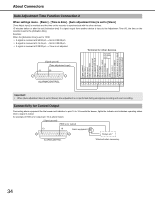
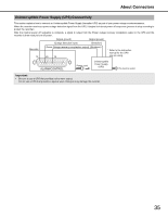
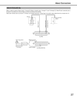
About Connectors Using the Alarm/Control connector You can use emergency recording and auto adjustment time functions when alarm equipment like a buzzer or indicator which is mounted externally. Create the connector by referring to the pin assignments. Pin Assignments The pin assignments are different for other Network Disk Recorders. Connect using the following chart. 13 1 ALARM/CONTROL 25 14 Pin Number 1 2 3 4 5 6 7 8 9 10 11 12 13 14 15 16 17 18 19 20 21 Name Alarm input 8 Alarm input 9 Alarm input 10 Alarm input 11 Alarm input 12 Alarm input 13 Alarm input 14 Alarm input 15 Alarm input 16 Network error output Alarm reset input Emergency recording input Signal ground Signal ground Available disk space warning output HDD error output Camera error output Error output Power outage recovery completion output Time adjustment input/ output Alarm output Description of Operation Remarks Event action will be performed according to the Non-voltage make contact input 5V settings. pull-up 150 kΩ Signal output upon detection of a broken Ethernet Open collector output 24 V DC max., link. 100 mA Signal output upon DHCP IP address expiration. Canceling the alarm display Starting emergency recording signal input Non-voltage make contact input 5V pull-up 150 kΩ Signal output for available disk space warning of Open collector output 24 V DC max., the recording/copy area 100 mA Signal output upon detection of a HDD error Signal output upon detection of a camera error Signal output upon detection of a unit error Signal output upon completion of outage processing High (+5 V - +12 V, 6.3 mA max.) The time of this unit is adjusted to the preset time according to the signal input. This signal output is then generated for the setting time of this unit. Time of all other units is adjusted to the setting time of this unit. 52 kΩ 5 V pull-up, Output current -100 mA/Non-voltage make contact input Alarm signal output at an event occurrence Open collector output 24 V DC max., 100 mA 32
-
 1
1 -
2
-
3
-
4
-
5
-
6
-
7
-
8
-
9
-
10
-
11
-
12
-
13
-
14
-
15
-
16
-
17
-
18
-
19
-
20
-
21
-
22
-
23
-
24
-
25
-
26
-
27
-
28
-
29
-
30
-
31
-
32
-
33
-
34
-
35
-
36
-
37
-
38
-
39
-
40
-
41
-
42
-
43
-
44
-
45
-
46
-
47
-
48
-
49
-
50
-
51
-
52
-
53
-
54
-
55
-
56
-
57
-
58
-
59
-
60
-
61
-
62
-
63
-
64
-
65
-
66
-
67
-
68
-
69
-
70
-
71
-
72
-
73
-
74
-
75
-
76
-
77
-
78
-
79
-
80
-
81
-
82
-
83
-
84
-
85
-
86
-
87
-
88
-
89
-
90
-
91
-
92
-
93
-
94
-
95
-
 96
96 -
 97
97 -
 98
98 -
 99
99 -
 100
100 -
 101
101 -
 102
102 -
 103
103 -
 104
104 -
 105
105 -
 106
106 -
107
-
108
-
109
-
110
-
111
-
112
-
113
-
114
-
115
-
116
-
117
-
118
-
119
-
120
-
121
-
122
-
123
-
124
-
125
-
126
-
127
-
128
-
129
-
130
-
131
-
132
-
133
-
134
-
135
-
136
-
137
-
138
-
139
-
140
-
141
-
142
-
143
-
144
-
145
-
146
-
147
-
148
-
149
-
150
-
151
-
152
-
153
-
154
-
155
-
156
-
157
-
158
-
159
-
160
-
161
-
162
-
163
-
164
-
165
-
166
-
167
-
168
-
169
-
170
-
171
-
172
-
173
-
174
-
175
-
176
-
177
-
178
-
179
-
180
-
181
-
182
-
183
-
184
-
185
-
186
-
187
-
188
-
189
-
190
-
191
-
192
-
193
-
194
-
195
-
196
-
197
-
198
-
199
-
200
-
201
-
202
-
203
-
204
-
205
-
206
-
207
-
208
-
209
-
210
-
211
-
212
-
213
-
214
-
215
-
216
-
217
-
218
-
219
-
220
-
221
-
222
-
223
-
224
-
225
-
226
-
227
-
228
-
229
-
230
-
231
-
232
-
233
 |
 |
