Panasonic WJ-ND400K Operating Instructions - Page 84
Rear View, the Brace - wj hde400 g
 |
View all Panasonic WJ-ND400K manuals
Add to My Manuals
Save this manual to your list of manuals |
Page 84 highlights
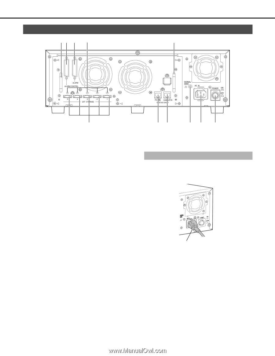
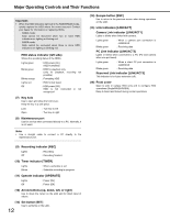
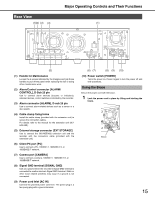
Rear View (1)(2) (3) (4) Major Operating Controls and Their Functions (1) (5) (1) Handle for Maintenance Loosen the 5 screws indicated by the triangles and grip these handles to pull off the panel when replacing the fan or doing other maintenance work. (2) Alarm/Control connector [ALARM/ CONTROL], D-Sub 25 pin Use to connect alarm devices (buzzers or indicators), external devices, control switches controlled by the recorder. (3) Alarm connector [ALARM], D-sub 25 pin Use to connect alarm-related devices such as a sensor or a door switch. (4) Cable clamp fixing holes Install the cable clamp (provided with the extension unit) to secure the connection cables. For details refer to the manual for the extension unit (WJHDE400). (5) External storage connector [EXT STORAGE] Use to connect the (WJ-HDE400) extension unit and the recorder with the connection cable (provided with the extension unit). (6) Client PC port [PC] Use to connect a PC, 10BASE-T, 100BASE-TX, or 1000BASE-T network. (7) Camera port [CAMERA] Use to connect a camera, 10BASE-T, 100BASE-TX, or 1000BASE-T network. (8) Signal GND terminal [SIGNAL GND] Use as a ground when the recorder's Signal GND terminal is connected to another device's Signal GND terminal. Static or other noise related problems may occur if a ground is not connected. (9) Power cord Inlet [AC IN] Connect the provided power cord here. The power plug is a two prong plug with a ground terminal. (6) (7) (8) (9) (10) (10) Power switch [POWER] Turns the power on. Press it again to turn the power off and end operations. Using the Brace Secure the power cord with the brace. 1 Lock the power cord in place by lifting and latching the brace. Brace 15
-
 1
1 -
2
-
3
-
4
-
5
-
6
-
7
-
8
-
9
-
10
-
11
-
12
-
13
-
14
-
15
-
16
-
17
-
18
-
19
-
20
-
21
-
22
-
23
-
24
-
25
-
26
-
27
-
28
-
29
-
30
-
31
-
32
-
33
-
34
-
35
-
36
-
37
-
38
-
39
-
40
-
41
-
42
-
43
-
44
-
45
-
46
-
47
-
48
-
49
-
50
-
51
-
52
-
53
-
54
-
55
-
56
-
57
-
58
-
59
-
60
-
61
-
62
-
63
-
64
-
65
-
66
-
67
-
68
-
69
-
70
-
71
-
72
-
73
-
74
-
75
-
76
-
77
-
78
-
 79
79 -
 80
80 -
 81
81 -
 82
82 -
 83
83 -
 84
84 -
 85
85 -
 86
86 -
 87
87 -
 88
88 -
 89
89 -
90
-
91
-
92
-
93
-
94
-
95
-
96
-
97
-
98
-
99
-
100
-
101
-
102
-
103
-
104
-
105
-
106
-
107
-
108
-
109
-
110
-
111
-
112
-
113
-
114
-
115
-
116
-
117
-
118
-
119
-
120
-
121
-
122
-
123
-
124
-
125
-
126
-
127
-
128
-
129
-
130
-
131
-
132
-
133
-
134
-
135
-
136
-
137
-
138
-
139
-
140
-
141
-
142
-
143
-
144
-
145
-
146
-
147
-
148
-
149
-
150
-
151
-
152
-
153
-
154
-
155
-
156
-
157
-
158
-
159
-
160
-
161
-
162
-
163
-
164
-
165
-
166
-
167
-
168
-
169
-
170
-
171
-
172
-
173
-
174
-
175
-
176
-
177
-
178
-
179
-
180
-
181
-
182
-
183
-
184
-
185
-
186
-
187
-
188
-
189
-
190
-
191
-
192
-
193
-
194
-
195
-
196
-
197
-
198
-
199
-
200
-
201
-
202
-
203
-
204
-
205
-
206
-
207
-
208
-
209
-
210
-
211
-
212
-
213
-
214
-
215
-
216
-
217
-
218
-
219
-
220
-
221
-
222
-
223
-
224
-
225
-
226
-
227
-
228
-
229
-
230
-
231
-
232
-
233
 |
 |