Panasonic WJ-ND400K Operating Instructions - Page 104
Uninterruptible Power Supply UPS Connectivity, ALARM/CO
 |
View all Panasonic WJ-ND400K manuals
Add to My Manuals
Save this manual to your list of manuals |
Page 104 highlights
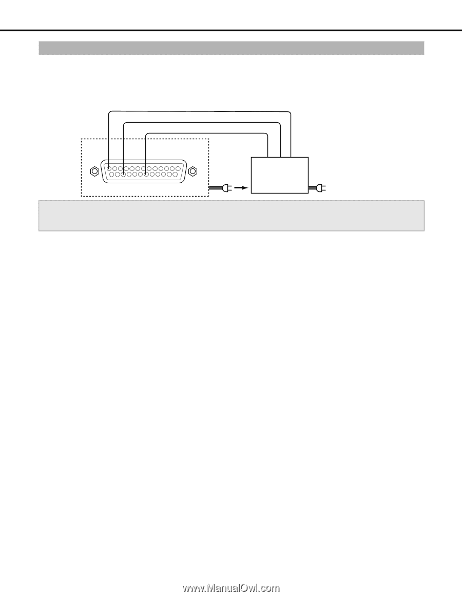
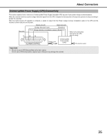
About Connectors Uninterruptible Power Supply (UPS) Connectivity This section explains how to connect an Uninterruptible Power Supply (hereafter UPS) as part of your power outage countermeasures. When the recorder receives a power outage detection signal from the UPS, it begins its internal power off sequence (process to stop recording to protect the recorder). After the internal power off sequence is complete, a signal is output from the Power outage recovery completion output to the UPS and the recorder is then ready to turn off power. (Signal ground) (Signal ground) (Outage detection input) (Detection) Recorder 13 (Power Outage recovery complection output) (Shutdown) 23 19 * Refer to the instruction manual for the UPS you are using. ALARM/CONTROL Power cord Uninterruptible Power Supply (UPS) To electric outlet Important: • Be sure to use a UPS that provides a sine-wave output. Do not use a UPS that provides a square wave. Doing so may damage the recorder. 35
-
 1
1 -
2
-
3
-
4
-
5
-
6
-
7
-
8
-
9
-
10
-
11
-
12
-
13
-
14
-
15
-
16
-
17
-
18
-
19
-
20
-
21
-
22
-
23
-
24
-
25
-
26
-
27
-
28
-
29
-
30
-
31
-
32
-
33
-
34
-
35
-
36
-
37
-
38
-
39
-
40
-
41
-
42
-
43
-
44
-
45
-
46
-
47
-
48
-
49
-
50
-
51
-
52
-
53
-
54
-
55
-
56
-
57
-
58
-
59
-
60
-
61
-
62
-
63
-
64
-
65
-
66
-
67
-
68
-
69
-
70
-
71
-
72
-
73
-
74
-
75
-
76
-
77
-
78
-
79
-
80
-
81
-
82
-
83
-
84
-
85
-
86
-
87
-
88
-
89
-
90
-
91
-
92
-
93
-
94
-
95
-
96
-
97
-
98
-
 99
99 -
 100
100 -
 101
101 -
 102
102 -
 103
103 -
 104
104 -
 105
105 -
 106
106 -
 107
107 -
 108
108 -
 109
109 -
110
-
111
-
112
-
113
-
114
-
115
-
116
-
117
-
118
-
119
-
120
-
121
-
122
-
123
-
124
-
125
-
126
-
127
-
128
-
129
-
130
-
131
-
132
-
133
-
134
-
135
-
136
-
137
-
138
-
139
-
140
-
141
-
142
-
143
-
144
-
145
-
146
-
147
-
148
-
149
-
150
-
151
-
152
-
153
-
154
-
155
-
156
-
157
-
158
-
159
-
160
-
161
-
162
-
163
-
164
-
165
-
166
-
167
-
168
-
169
-
170
-
171
-
172
-
173
-
174
-
175
-
176
-
177
-
178
-
179
-
180
-
181
-
182
-
183
-
184
-
185
-
186
-
187
-
188
-
189
-
190
-
191
-
192
-
193
-
194
-
195
-
196
-
197
-
198
-
199
-
200
-
201
-
202
-
203
-
204
-
205
-
206
-
207
-
208
-
209
-
210
-
211
-
212
-
213
-
214
-
215
-
216
-
217
-
218
-
219
-
220
-
221
-
222
-
223
-
224
-
225
-
226
-
227
-
228
-
229
-
230
-
231
-
232
-
233
 |
 |