Panasonic WJ-ND400K Operating Instructions - Page 80
Major Operatin, Controls and Their Functions, Front View
 |
View all Panasonic WJ-ND400K manuals
Add to My Manuals
Save this manual to your list of manuals |
Page 80 highlights
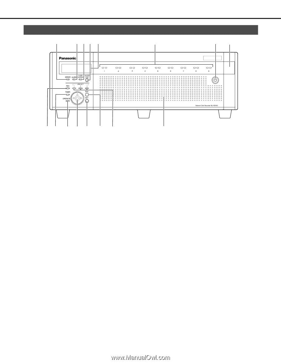
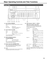
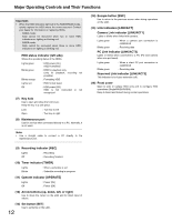
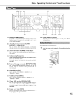
Major Operating Controls and Their Functions Front View (1) (2) (3)(4) (5) (6) (7) (8) (9) (10) (11) (12) (13) (14) (15) (1) Error indicator [ERROR] Blinks when errors or problems with the recorder's operation occur. Blinks red Blinks orange : System errors : Temperature is too high or low. Cooling fan stopped, etc. (2) Alarm indicator [ALARM] Blinks : Alarm has occurred Lights : Alarm output stopped Off : Alarm is resolved or no alarm has occurred Refer to the Operating Instructions (PDF file) for more information about alarms. (3) Alarm suspension indicator [ALARM SUSPEND] Lights : Alarm suspend stopped Off : Alarm is not suspended Refer to the Operating Instructions (PDF file) for more information about alarm suspension. (4) Buzzer stop button [BUZZER STOP] Use to turn off the buzzer after an alarm or error occurs. Refer to the Operating Instructions (PDF file) for more information about alarms and errors. (5) LCD Displays the recorder's status (errors etc.) and functions that are operated using the buttons on the front panel. (16) (6) HDD indicators ("HDD1" to "HDD9") HDD access indicator (right side) Indicates the access status and problems of the HDD. When errors occur on an HDD in RAID5/RAID6 mode, the indicator lights or blinks red. Blinks green : Accessing HDD Off : Not accessing HDD Lights red : Errors have occurred on the internal HDD (Data can be recovered by replacing HDD.) • When in RAID5 mode, the first HDD has errors • When using RAID6, the first two HDDs have errors. Blinks red : Errors have occurred on the internal HDD (Data cannot be recovered even if HDD is replaced) • When in RAID5 mode, the second HDD has errors • When in RAID6 mode, the third HDD has errors Lights orange and : Recovering data from drive in RAID5/ red RAID6 mode. (Alternately) (This indicator looks orange during high-speed processing.) The indicators display the status of the drives from HDD1 to HDD9, but if a system errors occur, each indicator has the same display. 11
-
 1
1 -
2
-
3
-
4
-
5
-
6
-
7
-
8
-
9
-
10
-
11
-
12
-
13
-
14
-
15
-
16
-
17
-
18
-
19
-
20
-
21
-
22
-
23
-
24
-
25
-
26
-
27
-
28
-
29
-
30
-
31
-
32
-
33
-
34
-
35
-
36
-
37
-
38
-
39
-
40
-
41
-
42
-
43
-
44
-
45
-
46
-
47
-
48
-
49
-
50
-
51
-
52
-
53
-
54
-
55
-
56
-
57
-
58
-
59
-
60
-
61
-
62
-
63
-
64
-
65
-
66
-
67
-
68
-
69
-
70
-
71
-
72
-
73
-
74
-
 75
75 -
 76
76 -
 77
77 -
 78
78 -
 79
79 -
 80
80 -
 81
81 -
 82
82 -
 83
83 -
 84
84 -
 85
85 -
86
-
87
-
88
-
89
-
90
-
91
-
92
-
93
-
94
-
95
-
96
-
97
-
98
-
99
-
100
-
101
-
102
-
103
-
104
-
105
-
106
-
107
-
108
-
109
-
110
-
111
-
112
-
113
-
114
-
115
-
116
-
117
-
118
-
119
-
120
-
121
-
122
-
123
-
124
-
125
-
126
-
127
-
128
-
129
-
130
-
131
-
132
-
133
-
134
-
135
-
136
-
137
-
138
-
139
-
140
-
141
-
142
-
143
-
144
-
145
-
146
-
147
-
148
-
149
-
150
-
151
-
152
-
153
-
154
-
155
-
156
-
157
-
158
-
159
-
160
-
161
-
162
-
163
-
164
-
165
-
166
-
167
-
168
-
169
-
170
-
171
-
172
-
173
-
174
-
175
-
176
-
177
-
178
-
179
-
180
-
181
-
182
-
183
-
184
-
185
-
186
-
187
-
188
-
189
-
190
-
191
-
192
-
193
-
194
-
195
-
196
-
197
-
198
-
199
-
200
-
201
-
202
-
203
-
204
-
205
-
206
-
207
-
208
-
209
-
210
-
211
-
212
-
213
-
214
-
215
-
216
-
217
-
218
-
219
-
220
-
221
-
222
-
223
-
224
-
225
-
226
-
227
-
228
-
229
-
230
-
231
-
232
-
233
 |
 |