Panasonic WJ-ND400K Operating Instructions - Page 112
Settin, the IP Address, and Cancelin, Key Lock, Confi, the Settin, s for Each Item
 |
View all Panasonic WJ-ND400K manuals
Add to My Manuals
Save this manual to your list of manuals |
Page 112 highlights
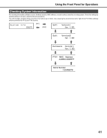
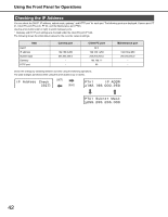
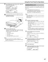
Using the Front Panel for Operations Setting the IP Address Settable items are the same as those in "Checking the IP Address (page 42)". Configure the settings for each item by switching between screens using the following operations. When the cursor is ">", use the arrow buttons (up or down) to switch between screens. The cursor is shown with an under bar (_). The ports are displayed as follows: Camera port: PT #1, Client PC port: PT #2, and Maintenance port: PT #3. Use the arrow buttons (left or right) to switch between ports. Gateway and HTTP port settings are configured under the client PC port (PT #2). The LCD changes as follows when using the arrow buttons (up or down). [SET] [ESC] Important: • Always configure the network settings for the ports using different subnet masks. Using the same subnet mask may result in improper network communication. Configuring the Settings for Each Item 1 Click the [SET] button when the cursor is [>]. The cursor moves to the number area. • When the cursor is ">" and you press the arrow buttons (left or right), the PT #2 and PT #3 screens are displayed and you can select other ports. 2 Move the cursor using the arrow buttons (up or down) and enter values using (up or down). 3 Press the [ESC] button to move the cursor to ">" and check the settings. Setting and Canceling Key Lock You can lock the buttons on the front panel to prevent them from being operated. Press the [SET] button on the Key Lock Setting screen to lock the keys. [Keylock Enabled] is displayed. Then, it returns to the display format screen. [SET] To cancel the key lock, enter the password (default: 12345) on the Password Entry screen. You can change the password on the settings menu. Refer to the Setup Instructions (PDF file) for more information. 43
-
 1
1 -
2
-
3
-
4
-
5
-
6
-
7
-
8
-
9
-
10
-
11
-
12
-
13
-
14
-
15
-
16
-
17
-
18
-
19
-
20
-
21
-
22
-
23
-
24
-
25
-
26
-
27
-
28
-
29
-
30
-
31
-
32
-
33
-
34
-
35
-
36
-
37
-
38
-
39
-
40
-
41
-
42
-
43
-
44
-
45
-
46
-
47
-
48
-
49
-
50
-
51
-
52
-
53
-
54
-
55
-
56
-
57
-
58
-
59
-
60
-
61
-
62
-
63
-
64
-
65
-
66
-
67
-
68
-
69
-
70
-
71
-
72
-
73
-
74
-
75
-
76
-
77
-
78
-
79
-
80
-
81
-
82
-
83
-
84
-
85
-
86
-
87
-
88
-
89
-
90
-
91
-
92
-
93
-
94
-
95
-
96
-
97
-
98
-
99
-
100
-
101
-
102
-
103
-
104
-
105
-
106
-
 107
107 -
 108
108 -
 109
109 -
 110
110 -
 111
111 -
 112
112 -
 113
113 -
 114
114 -
 115
115 -
 116
116 -
 117
117 -
118
-
119
-
120
-
121
-
122
-
123
-
124
-
125
-
126
-
127
-
128
-
129
-
130
-
131
-
132
-
133
-
134
-
135
-
136
-
137
-
138
-
139
-
140
-
141
-
142
-
143
-
144
-
145
-
146
-
147
-
148
-
149
-
150
-
151
-
152
-
153
-
154
-
155
-
156
-
157
-
158
-
159
-
160
-
161
-
162
-
163
-
164
-
165
-
166
-
167
-
168
-
169
-
170
-
171
-
172
-
173
-
174
-
175
-
176
-
177
-
178
-
179
-
180
-
181
-
182
-
183
-
184
-
185
-
186
-
187
-
188
-
189
-
190
-
191
-
192
-
193
-
194
-
195
-
196
-
197
-
198
-
199
-
200
-
201
-
202
-
203
-
204
-
205
-
206
-
207
-
208
-
209
-
210
-
211
-
212
-
213
-
214
-
215
-
216
-
217
-
218
-
219
-
220
-
221
-
222
-
223
-
224
-
225
-
226
-
227
-
228
-
229
-
230
-
231
-
232
-
233
 |
 |
