Panasonic WJ-ND400K Operating Instructions - Page 106
Alarm Connectivity, ALARM, ipment, Relays etc., Alarm inp, Signal gro, Sensor, Door sec, switch
 |
View all Panasonic WJ-ND400K manuals
Add to My Manuals
Save this manual to your list of manuals |
Page 106 highlights
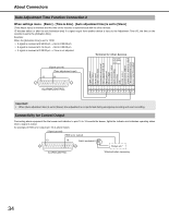
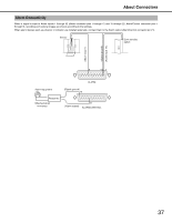
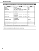
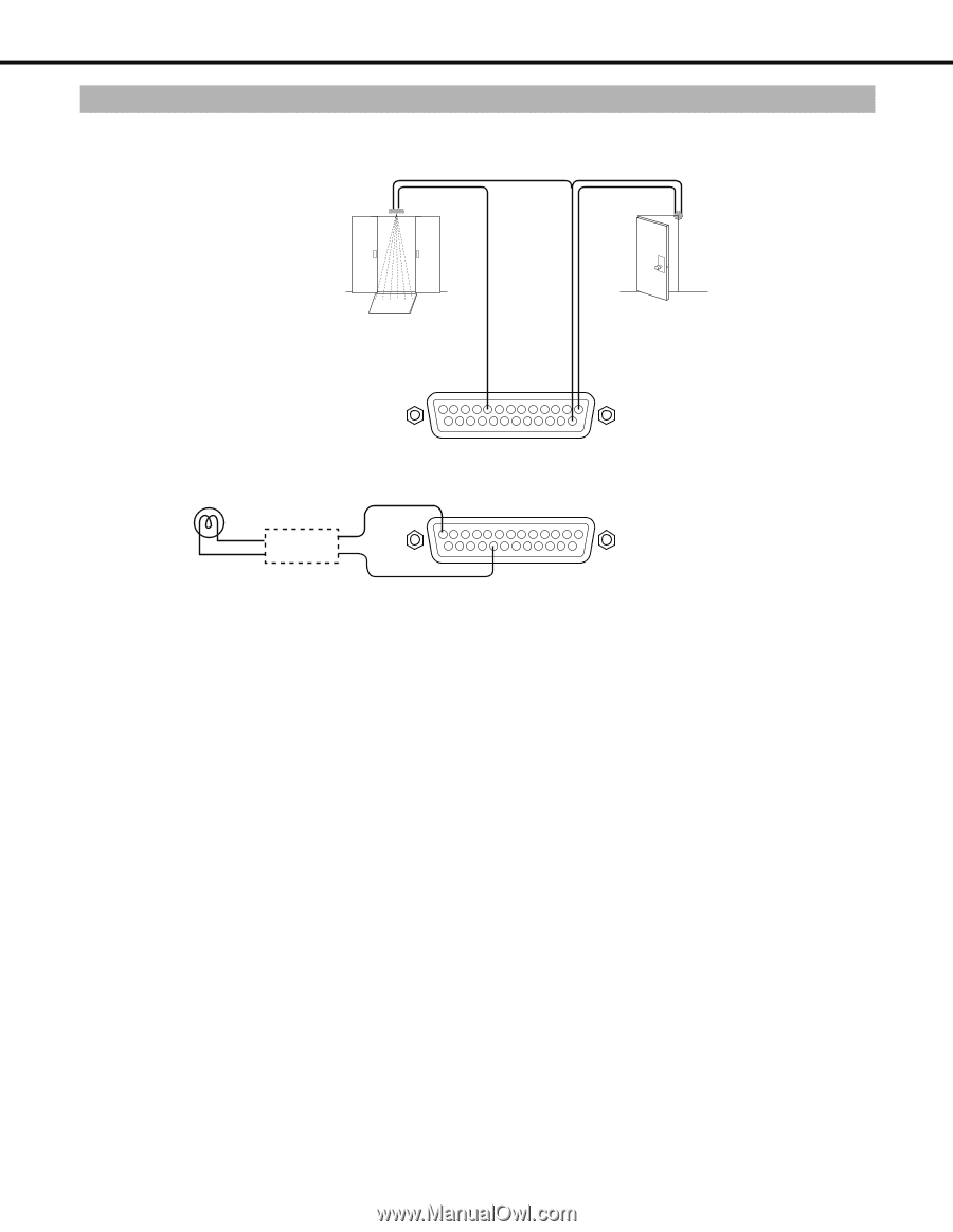
About Connectors Alarm Connectivity When a signal is input to Alarm Inputs 1 through 32 (Alarm connector pins 1 through 12 and 15 through 25, Alarm/Control connector pins 1 through 9), recording and camera images are shown according to the settings. When alarm devices such as a buzzer or indicator are installed externally, connect them to the Alarm output (Alarm/Control connector pin 21). Sensor Door security switch (Alarm input 1) (Signal ground) (Alarm input 17) 9 14 1 ALARM Alarm equipment (Signal ground) 13 Relays etc.* *Attached when necessary. 21 (Alarm output) ALARM/CONTROL 37
-
 1
1 -
2
-
3
-
4
-
5
-
6
-
7
-
8
-
9
-
10
-
11
-
12
-
13
-
14
-
15
-
16
-
17
-
18
-
19
-
20
-
21
-
22
-
23
-
24
-
25
-
26
-
27
-
28
-
29
-
30
-
31
-
32
-
33
-
34
-
35
-
36
-
37
-
38
-
39
-
40
-
41
-
42
-
43
-
44
-
45
-
46
-
47
-
48
-
49
-
50
-
51
-
52
-
53
-
54
-
55
-
56
-
57
-
58
-
59
-
60
-
61
-
62
-
63
-
64
-
65
-
66
-
67
-
68
-
69
-
70
-
71
-
72
-
73
-
74
-
75
-
76
-
77
-
78
-
79
-
80
-
81
-
82
-
83
-
84
-
85
-
86
-
87
-
88
-
89
-
90
-
91
-
92
-
93
-
94
-
95
-
96
-
97
-
98
-
99
-
100
-
 101
101 -
 102
102 -
 103
103 -
 104
104 -
 105
105 -
 106
106 -
 107
107 -
 108
108 -
 109
109 -
 110
110 -
 111
111 -
112
-
113
-
114
-
115
-
116
-
117
-
118
-
119
-
120
-
121
-
122
-
123
-
124
-
125
-
126
-
127
-
128
-
129
-
130
-
131
-
132
-
133
-
134
-
135
-
136
-
137
-
138
-
139
-
140
-
141
-
142
-
143
-
144
-
145
-
146
-
147
-
148
-
149
-
150
-
151
-
152
-
153
-
154
-
155
-
156
-
157
-
158
-
159
-
160
-
161
-
162
-
163
-
164
-
165
-
166
-
167
-
168
-
169
-
170
-
171
-
172
-
173
-
174
-
175
-
176
-
177
-
178
-
179
-
180
-
181
-
182
-
183
-
184
-
185
-
186
-
187
-
188
-
189
-
190
-
191
-
192
-
193
-
194
-
195
-
196
-
197
-
198
-
199
-
200
-
201
-
202
-
203
-
204
-
205
-
206
-
207
-
208
-
209
-
210
-
211
-
212
-
213
-
214
-
215
-
216
-
217
-
218
-
219
-
220
-
221
-
222
-
223
-
224
-
225
-
226
-
227
-
228
-
229
-
230
-
231
-
232
-
233
 |
 |
About Connectors
37
W
hen a signal is input to Alarm Inputs 1 through 32 (Alarm connector pins 1 through 12 and 15 through 25, Alarm/Control connector pins 1
through 9), recording and camera images are sho
w
n according to the settings.
W
hen alarm devices such as a
b
uzzer or indicator are installed externally, connect them to the Alarm output (Alarm/Control connector pin 21).
Alarm Connectivity
ALARM
21
9
Alarm eq
u
ipment
Relays etc.*
ALARM/CO
N
TROL
(Alarm inp
u
t 17)
(Signal gro
u
nd)
Sensor
Door sec
u
rity
switch
(Alarm inp
u
t 1)
(Alarm o
u
tp
u
t)
*Attached when
necessary.
(Signal gro
u
nd)
13
1
14