Panasonic WJ-ND400K Operating Instructions - Page 93
Rack mountin, positions - wj hde400 pdf
 |
View all Panasonic WJ-ND400K manuals
Add to My Manuals
Save this manual to your list of manuals |
Page 93 highlights
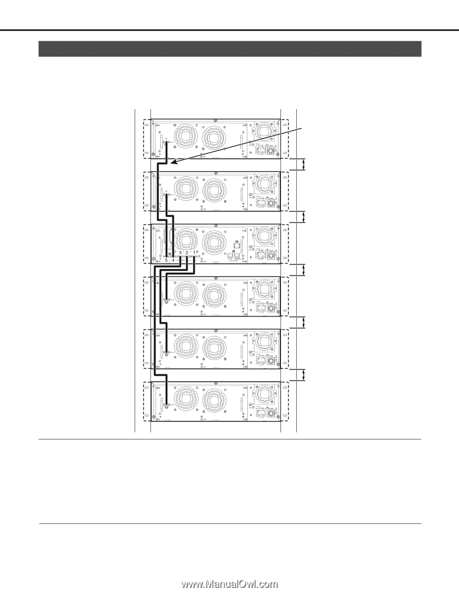
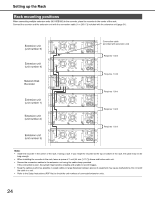
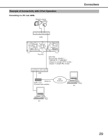
Setting up the Rack Rack mounting positions When connecting multiple extension units (WJ-HDE400) to the recorder, place the recorder in the center of the rack. Connect the recorder and the extension unit with the connection cable (1 m {39.4 "}) included with the extension unit (page 31). Extension unit (unit number 5) Extension unit (unit number 4) Network Disk Recorder Extension unit (unit number 1) Extension unit (unit number 2) Extension unit (unit number 3) Connection cable (provided with extension unit) Requires 1 Unit Requires 1 Unit Requires 1 Unit Requires 1 Unit Requires 1 Unit Note: • Install the recorder in the center of the rack, if using a rack. If you install the recorder at the top or bottom of the rack, the cable may not be long enough. • When installing the recorder in the rack, leave a space of 1 unit (44 mm {1.73 "}) above and below each unit. • Secure the connection cables to the extension unit using the cable clamp provided. If the connection is poor, the system may become unstable and unable to record images. • Keep the cables as short as possible. Looped cables or large distances between pieces of equipment may cause malfunctions. Do not wind the cable in a coil. • Refer to the Setup Instructions (PDF file) to check the unit numbers of connected extension units. 24
-
 1
1 -
2
-
3
-
4
-
5
-
6
-
7
-
8
-
9
-
10
-
11
-
12
-
13
-
14
-
15
-
16
-
17
-
18
-
19
-
20
-
21
-
22
-
23
-
24
-
25
-
26
-
27
-
28
-
29
-
30
-
31
-
32
-
33
-
34
-
35
-
36
-
37
-
38
-
39
-
40
-
41
-
42
-
43
-
44
-
45
-
46
-
47
-
48
-
49
-
50
-
51
-
52
-
53
-
54
-
55
-
56
-
57
-
58
-
59
-
60
-
61
-
62
-
63
-
64
-
65
-
66
-
67
-
68
-
69
-
70
-
71
-
72
-
73
-
74
-
75
-
76
-
77
-
78
-
79
-
80
-
81
-
82
-
83
-
84
-
85
-
86
-
87
-
 88
88 -
 89
89 -
 90
90 -
 91
91 -
 92
92 -
 93
93 -
 94
94 -
 95
95 -
 96
96 -
 97
97 -
 98
98 -
99
-
100
-
101
-
102
-
103
-
104
-
105
-
106
-
107
-
108
-
109
-
110
-
111
-
112
-
113
-
114
-
115
-
116
-
117
-
118
-
119
-
120
-
121
-
122
-
123
-
124
-
125
-
126
-
127
-
128
-
129
-
130
-
131
-
132
-
133
-
134
-
135
-
136
-
137
-
138
-
139
-
140
-
141
-
142
-
143
-
144
-
145
-
146
-
147
-
148
-
149
-
150
-
151
-
152
-
153
-
154
-
155
-
156
-
157
-
158
-
159
-
160
-
161
-
162
-
163
-
164
-
165
-
166
-
167
-
168
-
169
-
170
-
171
-
172
-
173
-
174
-
175
-
176
-
177
-
178
-
179
-
180
-
181
-
182
-
183
-
184
-
185
-
186
-
187
-
188
-
189
-
190
-
191
-
192
-
193
-
194
-
195
-
196
-
197
-
198
-
199
-
200
-
201
-
202
-
203
-
204
-
205
-
206
-
207
-
208
-
209
-
210
-
211
-
212
-
213
-
214
-
215
-
216
-
217
-
218
-
219
-
220
-
221
-
222
-
223
-
224
-
225
-
226
-
227
-
228
-
229
-
230
-
231
-
232
-
233
 |
 |