Panasonic WJ-ND400K Operating Instructions - Page 102
Connectivity for Emer, ency Recordin, Connectivity for Switchin, to External Recordin
 |
View all Panasonic WJ-ND400K manuals
Add to My Manuals
Save this manual to your list of manuals |
Page 102 highlights
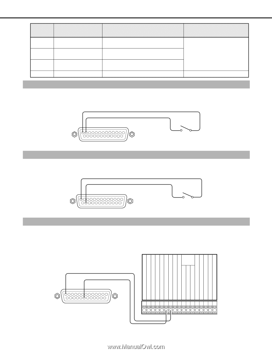
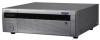
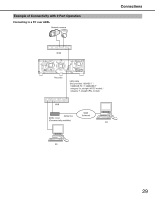
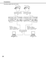
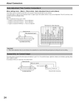
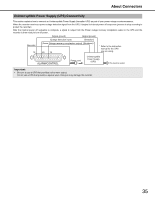
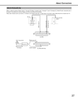
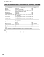
About Connectors Pin Number 22 23 24 25 Name Description of Operation Remarks Alarm suspension input The state of alarm suspension is assumed Non-voltage make contact input 5V according to the signal input. pull-up 150 kΩ Outage detection input Start of outage processing according to the signal input. External recording mode Changeover to the external recording mode switching input +5 V output +5 V output 200 mA max. Connectivity for Emergency Recording Turning [On] the external switch starts emergency recording. Emergency recording operations differ depending on the [Emergency rec.] settings accessed through the Setup menu (refer to Setup Instructions (PDF file)). (Signal ground) (Emergency recording input) 13 12 ALARM/CONTROL External switch Connectivity for Switching to External Recording Turning [On] the external switch, records by switching the program. Set the recording program in [Time table setup (Ext.)] under [Time table] on the settings menu (refer to Setup Instructions (PDF file)). (Signal ground) (External recording mode switching) 13 24 ALARM/CONTROL Auto Adjustment Time Function Connection 1 External switch When settings menu - [Basic] - [Time & date] - [Auto adjustment time] is set to [Master] [Time Adjust Output] is available and the time on other devices is synchronized with the recorder. When the time set under [Activation time] is reached, a signal is output from the Time adjustment input/output (pin no. 20). Terminal for other devices Front panel LED monitor output (Signal ground) (Time adjustment output) 13 20 Signal ground Sensor input Alarm Input Alarm reset input Series recording input Time adjustment input Signal ground Alarm output Alarm restore output Alarm recording Recording Disk Buzzer output System error output Temperature warning output Time adjustment output Series recording output ALARM/CONTROL 33
-
 1
1 -
2
-
3
-
4
-
5
-
6
-
7
-
8
-
9
-
10
-
11
-
12
-
13
-
14
-
15
-
16
-
17
-
18
-
19
-
20
-
21
-
22
-
23
-
24
-
25
-
26
-
27
-
28
-
29
-
30
-
31
-
32
-
33
-
34
-
35
-
36
-
37
-
38
-
39
-
40
-
41
-
42
-
43
-
44
-
45
-
46
-
47
-
48
-
49
-
50
-
51
-
52
-
53
-
54
-
55
-
56
-
57
-
58
-
59
-
60
-
61
-
62
-
63
-
64
-
65
-
66
-
67
-
68
-
69
-
70
-
71
-
72
-
73
-
74
-
75
-
76
-
77
-
78
-
79
-
80
-
81
-
82
-
83
-
84
-
85
-
86
-
87
-
88
-
89
-
90
-
91
-
92
-
93
-
94
-
95
-
96
-
 97
97 -
 98
98 -
 99
99 -
 100
100 -
 101
101 -
 102
102 -
 103
103 -
 104
104 -
 105
105 -
 106
106 -
 107
107 -
108
-
109
-
110
-
111
-
112
-
113
-
114
-
115
-
116
-
117
-
118
-
119
-
120
-
121
-
122
-
123
-
124
-
125
-
126
-
127
-
128
-
129
-
130
-
131
-
132
-
133
-
134
-
135
-
136
-
137
-
138
-
139
-
140
-
141
-
142
-
143
-
144
-
145
-
146
-
147
-
148
-
149
-
150
-
151
-
152
-
153
-
154
-
155
-
156
-
157
-
158
-
159
-
160
-
161
-
162
-
163
-
164
-
165
-
166
-
167
-
168
-
169
-
170
-
171
-
172
-
173
-
174
-
175
-
176
-
177
-
178
-
179
-
180
-
181
-
182
-
183
-
184
-
185
-
186
-
187
-
188
-
189
-
190
-
191
-
192
-
193
-
194
-
195
-
196
-
197
-
198
-
199
-
200
-
201
-
202
-
203
-
204
-
205
-
206
-
207
-
208
-
209
-
210
-
211
-
212
-
213
-
214
-
215
-
216
-
217
-
218
-
219
-
220
-
221
-
222
-
223
-
224
-
225
-
226
-
227
-
228
-
229
-
230
-
231
-
232
-
233
 |
 |