Panasonic WJ-ND400K Operating Instructions - Page 103
Auto Adjustment Time Function Connection 2, Connectivity for Control Output, When settin
 |
View all Panasonic WJ-ND400K manuals
Add to My Manuals
Save this manual to your list of manuals |
Page 103 highlights
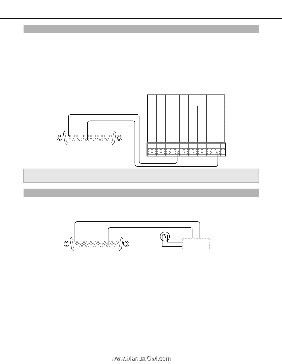
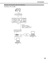
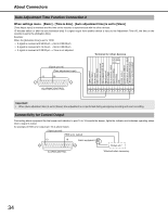
About Connectors Auto Adjustment Time Function Connection 2 When settings menu - [Basic] - [Time & date] - [Auto adjustment time] is set to [Slave] [Time Adjust Input] is available and the time on the recorder is synchronized with the other devices. 15 minutes before or after the set [Activation time] if a signal output from another device is input to the Adjustment Time I/O, the time on the recorder is set to the [Activation time]. Example: When the [Activation time] is set to 15:00 • A signal is received at 2:50:00 pm → Set to 3:00:00 pm • A signal is received at 3:14:45 pm → Set to 3:00:00 pm • A signal is received at 3:20:00 pm → Time is not adjusted. Terminal for other devices Front panel LED monitor output (Signal ground) (Time adjustment input) 13 20 Signal ground Sensor input Alarm Input Alarm reset input Series recording input Time adjustment input Signal ground Alarm output Alarm restore output Alarm recording Recording Disk Buzzer output System error output Temperature warning output Time adjustment output Series recording output ALARM/CONTROL Important: • When [Auto adjustment time] is set to [Slave], time adjustment is not performed during emergency recording and event recording. Connectivity for Control Output Connecting alarm equipment like the buzzer and indicator to pins 15 to 18 sounds the buzzer, lights the indicator and indicates operating status when a signal is output. An example of HDD error output (pin 16) is shown below. (Signal ground) (HDD error output) 13 16 Alarm equipment Relays etc.* ALARM/CONTROL *Attached when necessary. 34
-
 1
1 -
2
-
3
-
4
-
5
-
6
-
7
-
8
-
9
-
10
-
11
-
12
-
13
-
14
-
15
-
16
-
17
-
18
-
19
-
20
-
21
-
22
-
23
-
24
-
25
-
26
-
27
-
28
-
29
-
30
-
31
-
32
-
33
-
34
-
35
-
36
-
37
-
38
-
39
-
40
-
41
-
42
-
43
-
44
-
45
-
46
-
47
-
48
-
49
-
50
-
51
-
52
-
53
-
54
-
55
-
56
-
57
-
58
-
59
-
60
-
61
-
62
-
63
-
64
-
65
-
66
-
67
-
68
-
69
-
70
-
71
-
72
-
73
-
74
-
75
-
76
-
77
-
78
-
79
-
80
-
81
-
82
-
83
-
84
-
85
-
86
-
87
-
88
-
89
-
90
-
91
-
92
-
93
-
94
-
95
-
96
-
97
-
 98
98 -
 99
99 -
 100
100 -
 101
101 -
 102
102 -
 103
103 -
 104
104 -
 105
105 -
 106
106 -
 107
107 -
 108
108 -
109
-
110
-
111
-
112
-
113
-
114
-
115
-
116
-
117
-
118
-
119
-
120
-
121
-
122
-
123
-
124
-
125
-
126
-
127
-
128
-
129
-
130
-
131
-
132
-
133
-
134
-
135
-
136
-
137
-
138
-
139
-
140
-
141
-
142
-
143
-
144
-
145
-
146
-
147
-
148
-
149
-
150
-
151
-
152
-
153
-
154
-
155
-
156
-
157
-
158
-
159
-
160
-
161
-
162
-
163
-
164
-
165
-
166
-
167
-
168
-
169
-
170
-
171
-
172
-
173
-
174
-
175
-
176
-
177
-
178
-
179
-
180
-
181
-
182
-
183
-
184
-
185
-
186
-
187
-
188
-
189
-
190
-
191
-
192
-
193
-
194
-
195
-
196
-
197
-
198
-
199
-
200
-
201
-
202
-
203
-
204
-
205
-
206
-
207
-
208
-
209
-
210
-
211
-
212
-
213
-
214
-
215
-
216
-
217
-
218
-
219
-
220
-
221
-
222
-
223
-
224
-
225
-
226
-
227
-
228
-
229
-
230
-
231
-
232
-
233
 |
 |