Canon EOS C700 FF PL EOS C700 EOS C700 PL EOS C700 GS PL EOS C700 FF EOS C700 - Page 107
Reference Video Signal Output, Time Code Signal Output
 |
View all Canon EOS C700 FF PL manuals
Add to My Manuals
Save this manual to your list of manuals |
Page 107 highlights
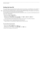
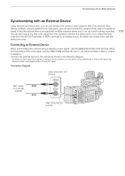
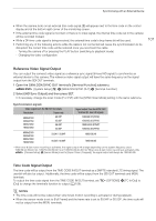
Synchronizing with an External Device • When the camera locks on an external time code signal, [E] will appear next to the time code on the control display and at the bottom right corner of the monitoring screen. • If the external time code signal is incorrect or there is no input signal, the internal time code set in the camera will be recorded instead. • While a DF time code signal is being received, the external time code's drop-frame bit will be used. • Performing any of the following actions while the cable is not connected will cause the synchronization to be disrupted; the correct time code will be restored once you reconnect the cable. - Turning the camera off or pressing the PLAY button (switching to playback mode) - Changing the video configuration 107 Reference Video Signal Output You can output the camera's video signal as a reference sync signal (tri-level HD signal) to synchronize an external device to this camera. The reference video signal output will have the same frequency as the signal output from the SDI OUT terminals. 1 Open the GENLOCK/SYNC OUT terminal's [Terminal Function] submenu. [System Setup] (B) > [GENLOCK/SYNC OUT] > [Terminal Function] 2 Select [HD Sync Output] and then press SET. • If necessary, change the scan mode (P or PsF) with the [SYNC Scan Mode] setting in the same submenu. Synchronization signals Video output from the SDI OUT terminals Resolution Frame rate 4096x2160 3840x2160 2048x1080 1920x1080 29.97P 25.00P 24.00P 23.98P 4096x2160 3840x2160 2048x1080 1920x1080 59.94i / 59.94P 50.00i / 50.00P Signal output from the SYNC OUT terminal (tri-level HD signal) 1080/29.97 (P/PsF) 1080/25.00 (P/PsF) 1080/24.00 (P/PsF)* 1080/23.98 (P/PsF) 1080/59.94i 1080/50.00i * When slow & fast motion recording is activated, the signal output will change depending on the system frequency used: 1080/59.94i (59.94 Hz), 1080/50.00i (50.00 Hz) or 1080/60.00i (24.00 Hz). When slow & fast motion recording is activated while [Camera Setup] > [Sensor Mode] is set to [Super 16mm (Cropped)], the signal output will always be 1080/60.00i. Time Code Signal Output The time code will be output from the TIME CODE IN/OUT terminal as a SMPTE-standard LTC timing signal. The user bit will also be output. Additionally, the time code will be output from the SDI OUT terminals and MON. terminals. To output the time code signal from the TIME CODE IN/OUT terminal, set [OPTIONS] > [TC In/Out] to [Out] to change the terminal's function to output (A 106). NOTES • The time code will not be output when slow & fast motion recording is activated or during playback. • When the sensor mode is set to [Full Frame] and the frame rate is set to 59.94P or 50.00P, the time code will not be output from the MON. terminals.
-
 1
1 -
2
-
3
-
4
-
5
-
6
-
7
-
8
-
9
-
10
-
11
-
12
-
13
-
14
-
15
-
16
-
17
-
18
-
19
-
20
-
21
-
22
-
23
-
24
-
25
-
26
-
27
-
28
-
29
-
30
-
31
-
32
-
33
-
34
-
35
-
36
-
37
-
38
-
39
-
40
-
41
-
42
-
43
-
44
-
45
-
46
-
47
-
48
-
49
-
50
-
51
-
52
-
53
-
54
-
55
-
56
-
57
-
58
-
59
-
60
-
61
-
62
-
63
-
64
-
65
-
66
-
67
-
68
-
69
-
70
-
71
-
72
-
73
-
74
-
75
-
76
-
77
-
78
-
79
-
80
-
81
-
82
-
83
-
84
-
85
-
86
-
87
-
88
-
89
-
90
-
91
-
92
-
93
-
94
-
95
-
96
-
97
-
98
-
99
-
100
-
101
-
 102
102 -
 103
103 -
 104
104 -
 105
105 -
 106
106 -
 107
107 -
 108
108 -
 109
109 -
 110
110 -
 111
111 -
 112
112 -
113
-
114
-
115
-
116
-
117
-
118
-
119
-
120
-
121
-
122
-
123
-
124
-
125
-
126
-
127
-
128
-
129
-
130
-
131
-
132
-
133
-
134
-
135
-
136
-
137
-
138
-
139
-
140
-
141
-
142
-
143
-
144
-
145
-
146
-
147
-
148
-
149
-
150
-
151
-
152
-
153
-
154
-
155
-
156
-
157
-
158
-
159
-
160
-
161
-
162
-
163
-
164
-
165
-
166
-
167
-
168
-
169
-
170
-
171
-
172
-
173
-
174
-
175
-
176
-
177
-
178
-
179
-
180
-
181
-
182
-
183
-
184
-
185
-
186
-
187
-
188
-
189
-
190
-
191
-
192
-
193
-
194
-
195
-
196
-
197
-
198
-
199
-
200
-
201
-
202
-
203
-
204
-
205
-
206
-
207
-
208
-
209
-
210
-
211
-
212
-
213
-
214
-
215
-
216
-
217
-
218
-
219
-
220
-
221
-
222
-
223
-
224
-
225
-
226
-
227
-
228
-
229
-
230
-
231
-
232
-
233
-
234
-
235
-
236
-
237
-
238
-
239
-
240
-
241
-
242
-
243
-
244
-
245
-
246
-
247
-
248
-
249
-
250
-
251
-
252
-
253
-
254
-
255
 |
 |