Canon EOS C700 FF PL EOS C700 EOS C700 PL EOS C700 GS PL EOS C700 FF EOS C700 - Page 115
Waveform Monitor, Displaying the Waveform Monitor
 |
View all Canon EOS C700 FF PL manuals
Add to My Manuals
Save this manual to your list of manuals |
Page 115 highlights
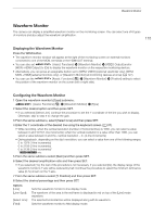
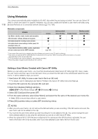
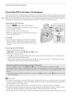
Waveform Monitor Waveform Monitor The camera can display a simplified waveform monitor on the monitoring screen. You can select one of 6 types of monitors and also adjust the waveform amplification. 115 Displaying the Waveform Monitor Press the WFM button. • The waveform monitor window will appear at the right of the monitoring screen on external monitors connected to one of the MON. terminals or the HDMI OUT terminal. • You can also set [Assist. Functions] > [Waveform Monitor] > [VIDEO Output] and/or [MON.+HDMI Output] to [On] to display the waveform monitor on the respective monitoring devices. • Alternatively, you can press an assignable button set to [WFM: VIDEO] (optional viewfinder only), [WFM: MON.+HDMI] (external monitors only), or [Waveform Monitor] (all monitoring devices at once) (A 127). • You can use the [Assist. Functions] (A) > [Waveform Monitor] > [Position] setting to select the position of the waveform monitor on the screen (left or right side). Configuring the Waveform Monitor 1 Open the waveform monitor's [Type] submenu. [Assist. Functions] (A) > [Waveform Monitor] > [Type] 2 Select the desired option and then press SET. • If you selected [Select Line], continue the procedure to set the Y coordinate of the line you wish to display. Otherwise, skip to step 5 to change the gain. 3 From the same submenu, select [Select Line] and then press SET. 4 Enter the Y coordinate of the desired line using the keyboard screen (A 37). • While recording, when the vertical resolution (number of horizontal lines) is 1080, you can select a value between 0 and 1079 (1-line increments); when the vertical resolution is a value other than 1080, you can select a value between 0 and the (2-line increments). • During playback, depending on the clip's resolution, you can select a value from one of the following ranges. 0 to 1079 (1-line increments) 0 to 2158 (2-line increments) 0 to 3138 (2-line increments)* * qr only. 5 From the same submenu select [Gain] and then press SET. 6 Select the desired amplification ratio and then press SET. • If you selected [1x], the rest of the procedure is not necessary. If you selected [2x], the display range of the waveform monitor's Y axis will be reduced by half. Continue the procedure to select the minimum luminance value (in %) shown on the Y axis. 7 From the same submenu select [Y Position] and then press SET. 8 Select the desired percentage and then press SET. Options [Line]: [Line+Spot]: [Select Line]: [Field]: Sets the waveform monitor to line display mode. The waveform of the area in the red frame is displayed in red on top of the [Line] mode waveform. The selected horizontal line will be displayed along with its waveform. Sets the waveform monitor to field display mode.
-
 1
1 -
2
-
3
-
4
-
5
-
6
-
7
-
8
-
9
-
10
-
11
-
12
-
13
-
14
-
15
-
16
-
17
-
18
-
19
-
20
-
21
-
22
-
23
-
24
-
25
-
26
-
27
-
28
-
29
-
30
-
31
-
32
-
33
-
34
-
35
-
36
-
37
-
38
-
39
-
40
-
41
-
42
-
43
-
44
-
45
-
46
-
47
-
48
-
49
-
50
-
51
-
52
-
53
-
54
-
55
-
56
-
57
-
58
-
59
-
60
-
61
-
62
-
63
-
64
-
65
-
66
-
67
-
68
-
69
-
70
-
71
-
72
-
73
-
74
-
75
-
76
-
77
-
78
-
79
-
80
-
81
-
82
-
83
-
84
-
85
-
86
-
87
-
88
-
89
-
90
-
91
-
92
-
93
-
94
-
95
-
96
-
97
-
98
-
99
-
100
-
101
-
102
-
103
-
104
-
105
-
106
-
107
-
108
-
109
-
 110
110 -
 111
111 -
 112
112 -
 113
113 -
 114
114 -
 115
115 -
 116
116 -
 117
117 -
 118
118 -
 119
119 -
 120
120 -
121
-
122
-
123
-
124
-
125
-
126
-
127
-
128
-
129
-
130
-
131
-
132
-
133
-
134
-
135
-
136
-
137
-
138
-
139
-
140
-
141
-
142
-
143
-
144
-
145
-
146
-
147
-
148
-
149
-
150
-
151
-
152
-
153
-
154
-
155
-
156
-
157
-
158
-
159
-
160
-
161
-
162
-
163
-
164
-
165
-
166
-
167
-
168
-
169
-
170
-
171
-
172
-
173
-
174
-
175
-
176
-
177
-
178
-
179
-
180
-
181
-
182
-
183
-
184
-
185
-
186
-
187
-
188
-
189
-
190
-
191
-
192
-
193
-
194
-
195
-
196
-
197
-
198
-
199
-
200
-
201
-
202
-
203
-
204
-
205
-
206
-
207
-
208
-
209
-
210
-
211
-
212
-
213
-
214
-
215
-
216
-
217
-
218
-
219
-
220
-
221
-
222
-
223
-
224
-
225
-
226
-
227
-
228
-
229
-
230
-
231
-
232
-
233
-
234
-
235
-
236
-
237
-
238
-
239
-
240
-
241
-
242
-
243
-
244
-
245
-
246
-
247
-
248
-
249
-
250
-
251
-
252
-
253
-
254
-
255
 |
 |