Canon EOS C700 FF PL EOS C700 EOS C700 PL EOS C700 GS PL EOS C700 FF EOS C700 - Page 99
Displaying Zebra Patterns, Select [VIDEO Output] and/or [MON.+HDMI Output]
 |
View all Canon EOS C700 FF PL manuals
Add to My Manuals
Save this manual to your list of manuals |
Page 99 highlights
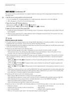
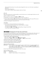
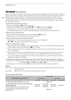
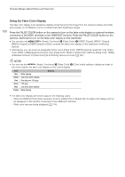
Onscreen Markers, Zebra Patterns and False Color To set the aspect ratio 1 Select [Aspect Ratio], select the desired option and then press SET. • If you selected one of the preset aspect ratios, the rest of the procedure is not necessary. If you selected [Custom], continue the procedure to set the desired aspect ratio. 99 2 Select [Custom Ratio] and then press SET. 3 Set the desired aspect ratio using the keyboard screen (A 37). To set the safe area If an aspect marker is not selected, the safe area will be calculated as a percentage of the whole image ([Whole Picture]) and you can only select the percentage (step 2). To calculate the safe area as a percentage of an aspect ratio marker ([Selected Aspect Marker]), select an aspect ratio marker in advance and perform the procedure from the beginning. 1 Select [Basis for Safe Area], select the desired option and then press SET. 2 Select [Safe Area %], select the desired percentage and then press SET. NOTES • The aspect ratio marker will not be displayed when the marker's ratio (including custom ratios) matches that of the resolution set in the video configuration. Displaying Zebra Patterns The camera has a zebra pattern function that shows black and white diagonal stripes over areas that are overexposed. There are two types of zebra patterns and you can display both simultaneously. Zebra 1 lets you identify areas within a certain range (±5% of a specified level from 5% to 95%) while zebra 2 lets you identify areas that are over a specified level (from 0% to 100%). When you display both simultaneously and they overlap, only the zebra 1 pattern will be displayed in those areas. Zebra 1 1 Open the [Zebra] submenu. [Assist. Functions] (A) > [Zebra] Zebra 2 2 Select [VIDEO Output] and/or [MON.+HDMI Output], select [On] and then press SET. • Alternatively, you can press an assignable button set to [Zebra: VIDEO] (optional viewfinder only), [Zebra: MON.+HDMI] (external monitors only) or [Zebra] (all monitoring devices at once) (A 127). • Select [Off] instead to not display the onscreen markers on the respective video outputs. 3 From the same submenu select [Select] to set the zebra pattern type. 4 Select [Zebra 1], [Zebra 2] or [Zebra 1+2] and then press SET. 5 From the same submenu select [Zebra 1 Level] or [Zebra 2 Level] to set the trigger level. 6 Select the desired value/range and then press SET. NOTES • When the HDMI OUT terminal's resolution is set to 4096x2160 or 3840x2160, zebra patterns will not be displayed on the monitor connected to the HDMI OUT terminal.
-
 1
1 -
2
-
3
-
4
-
5
-
6
-
7
-
8
-
9
-
10
-
11
-
12
-
13
-
14
-
15
-
16
-
17
-
18
-
19
-
20
-
21
-
22
-
23
-
24
-
25
-
26
-
27
-
28
-
29
-
30
-
31
-
32
-
33
-
34
-
35
-
36
-
37
-
38
-
39
-
40
-
41
-
42
-
43
-
44
-
45
-
46
-
47
-
48
-
49
-
50
-
51
-
52
-
53
-
54
-
55
-
56
-
57
-
58
-
59
-
60
-
61
-
62
-
63
-
64
-
65
-
66
-
67
-
68
-
69
-
70
-
71
-
72
-
73
-
74
-
75
-
76
-
77
-
78
-
79
-
80
-
81
-
82
-
83
-
84
-
85
-
86
-
87
-
88
-
89
-
90
-
91
-
92
-
93
-
 94
94 -
 95
95 -
 96
96 -
 97
97 -
 98
98 -
 99
99 -
 100
100 -
 101
101 -
 102
102 -
 103
103 -
 104
104 -
105
-
106
-
107
-
108
-
109
-
110
-
111
-
112
-
113
-
114
-
115
-
116
-
117
-
118
-
119
-
120
-
121
-
122
-
123
-
124
-
125
-
126
-
127
-
128
-
129
-
130
-
131
-
132
-
133
-
134
-
135
-
136
-
137
-
138
-
139
-
140
-
141
-
142
-
143
-
144
-
145
-
146
-
147
-
148
-
149
-
150
-
151
-
152
-
153
-
154
-
155
-
156
-
157
-
158
-
159
-
160
-
161
-
162
-
163
-
164
-
165
-
166
-
167
-
168
-
169
-
170
-
171
-
172
-
173
-
174
-
175
-
176
-
177
-
178
-
179
-
180
-
181
-
182
-
183
-
184
-
185
-
186
-
187
-
188
-
189
-
190
-
191
-
192
-
193
-
194
-
195
-
196
-
197
-
198
-
199
-
200
-
201
-
202
-
203
-
204
-
205
-
206
-
207
-
208
-
209
-
210
-
211
-
212
-
213
-
214
-
215
-
216
-
217
-
218
-
219
-
220
-
221
-
222
-
223
-
224
-
225
-
226
-
227
-
228
-
229
-
230
-
231
-
232
-
233
-
234
-
235
-
236
-
237
-
238
-
239
-
240
-
241
-
242
-
243
-
244
-
245
-
246
-
247
-
248
-
249
-
250
-
251
-
252
-
253
-
254
-
255
 |
 |