Canon EOS C700 FF PL EOS C700 EOS C700 PL EOS C700 GS PL EOS C700 FF EOS C700 - Page 16
INPUT terminals XLR: INPUT 1 top, INPUT 2, TIME CODE IN/OUT terminal
 |
View all Canon EOS C700 FF PL manuals
Add to My Manuals
Save this manual to your list of manuals |
Page 16 highlights
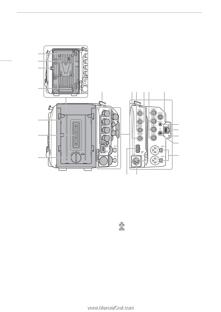
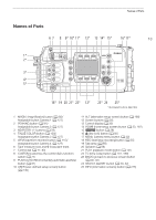
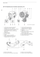
Names of Parts 16 (with the supplied battery adapter attached to the camera) 1 MON. 1 2 3 MON. 2 GENLOCK/ SYNC OUT TIME CODE IN/OUT HDMI OUT 4 8 9 10 1112 13 5 14 15 6 16 17 7 18 (with no extension module attached to the camera) 19 20 1 V-mount battery plate (A 26) 2 V-shaped battery mount (V-mount) 3 Battery release latch (A 26) 4 Battery contacts 5 Extension module mounting unit (A 23, 24) 6 Extension module connector 7 Compartment cover for the lithium button battery (A 24) 8 Cable clamp 9 TIME CODE IN/OUT terminal (A 105, 106, 107) 10 GENLOCK terminal (A 105, 106)/ SYNC OUT (synchronizing signal output) terminal (A 105, 107) 11 MON. terminals: MON. 1 (top), MON. 2 (bottom) (A 149, 153) 12 SDI OUT terminals: from top to bottom SDI OUT 1 to SDI OUT 4 (A 149, 152) 13 REMOTE B terminal 14 REMOTE A terminal For connecting the optional RC-V100 Remote Controller (A 123) or commercially available remote controllers. 15 (Ethernet) terminal (A 168) 16 (Ethernet) indicator 17 × (headphone) terminal (A 113, 143) 18 INPUT terminals (XLR): INPUT 1 (top), INPUT 2 (bottom) (A 109, 110) 19 HDMI OUT terminal (A 149, 154) 20 DC IN 12V terminal (A 27)
-
 1
1 -
2
-
3
-
4
-
5
-
6
-
7
-
8
-
9
-
10
-
 11
11 -
 12
12 -
 13
13 -
 14
14 -
 15
15 -
 16
16 -
 17
17 -
 18
18 -
 19
19 -
 20
20 -
 21
21 -
22
-
23
-
24
-
25
-
26
-
27
-
28
-
29
-
30
-
31
-
32
-
33
-
34
-
35
-
36
-
37
-
38
-
39
-
40
-
41
-
42
-
43
-
44
-
45
-
46
-
47
-
48
-
49
-
50
-
51
-
52
-
53
-
54
-
55
-
56
-
57
-
58
-
59
-
60
-
61
-
62
-
63
-
64
-
65
-
66
-
67
-
68
-
69
-
70
-
71
-
72
-
73
-
74
-
75
-
76
-
77
-
78
-
79
-
80
-
81
-
82
-
83
-
84
-
85
-
86
-
87
-
88
-
89
-
90
-
91
-
92
-
93
-
94
-
95
-
96
-
97
-
98
-
99
-
100
-
101
-
102
-
103
-
104
-
105
-
106
-
107
-
108
-
109
-
110
-
111
-
112
-
113
-
114
-
115
-
116
-
117
-
118
-
119
-
120
-
121
-
122
-
123
-
124
-
125
-
126
-
127
-
128
-
129
-
130
-
131
-
132
-
133
-
134
-
135
-
136
-
137
-
138
-
139
-
140
-
141
-
142
-
143
-
144
-
145
-
146
-
147
-
148
-
149
-
150
-
151
-
152
-
153
-
154
-
155
-
156
-
157
-
158
-
159
-
160
-
161
-
162
-
163
-
164
-
165
-
166
-
167
-
168
-
169
-
170
-
171
-
172
-
173
-
174
-
175
-
176
-
177
-
178
-
179
-
180
-
181
-
182
-
183
-
184
-
185
-
186
-
187
-
188
-
189
-
190
-
191
-
192
-
193
-
194
-
195
-
196
-
197
-
198
-
199
-
200
-
201
-
202
-
203
-
204
-
205
-
206
-
207
-
208
-
209
-
210
-
211
-
212
-
213
-
214
-
215
-
216
-
217
-
218
-
219
-
220
-
221
-
222
-
223
-
224
-
225
-
226
-
227
-
228
-
229
-
230
-
231
-
232
-
233
-
234
-
235
-
236
-
237
-
238
-
239
-
240
-
241
-
242
-
243
-
244
-
245
-
246
-
247
-
248
-
249
-
250
-
251
-
252
-
253
-
254
-
255
 |
 |