Dell PowerEdge FX2 Dell PowerEdge FN I/O Aggregator Command Line Reference Gui - Page 22
Link Aggregation, Link Tracking, VLANs, Uplink LAG
 |
View all Dell PowerEdge FX2 manuals
Add to My Manuals
Save this manual to your list of manuals |
Page 22 highlights
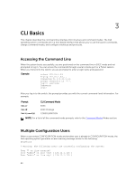
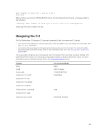
storm control on interfaces connected to an iSCSI equallogic (EQL) storage device, are applied automatically. CLI configuration is necessary only when the configuration includes iSCSI storage devices that cannot be automatically detected and when non-default QoS handling is required. Link Aggregation In Standalone, and VLT modes, all uplink ports (except port 9 in VLT mode) are configured in a single LAG (LAG 128). There can be multiple uplink LAGs in programmable-mux mode. Server-facing ports are autoconfigured as part of link aggregation groups if the corresponding server is configured for LACP-based NIC teaming. Static LAGs are supported in PMUX mode. NOTE: The recommended LACP timeout is Long-Timeout mode. Link Tracking By default, all server-facing ports are tracked by the operational status of the uplink LAG. If the uplink LAG goes down, the Aggregator loses its connectivity and is no longer operational; all server-facing ports are brought down. NOTE: If installed servers do not have connectivity to a ToR switch, check the Link Status LED of uplink ports on the Aggregator. If all LEDs are ON, check the LACP configuration on the ToR switch that is connected to the Aggregator to ensure the LACP is correctly configured. VLANs By default, all Aggregator ports belong to all 4094 VLANs and are members of untagged VLAN 1. You can use the CLI or CMC interface to configure only the required VLANs on a port. When you configure VLANs on server-facing interfaces (ports 1 to 8), you can assign VLANs to a port or a range of ports by entering the vlan tagged or vlan untagged commands in interface configuration mode; for example: Dell(conf)# interface tengigabitethernet 0/2 - 4 Dell(conf-if-range-te-0/2-4)# vlan tagged 5,7,10-12 Dell(conf-if-range-te-0/2-4)# vlan untagged 3 NOTE: You can also use the CMC interface to configure VLANs. Uplink LAG The tagged VLAN membership of the uplink LAG is automatically configured based on the tagged and untagged VLAN configuration of all server-facing ports (ports 1 to 8). The untagged VLAN used for the uplink LAG is always the default VLAN. 22
-
 1
1 -
2
-
3
-
4
-
5
-
6
-
7
-
8
-
9
-
10
-
11
-
12
-
13
-
14
-
15
-
16
-
 17
17 -
 18
18 -
 19
19 -
 20
20 -
 21
21 -
 22
22 -
 23
23 -
 24
24 -
 25
25 -
 26
26 -
 27
27 -
28
-
29
-
30
-
31
-
32
-
33
-
34
-
35
-
36
-
37
-
38
-
39
-
40
-
41
-
42
-
43
-
44
-
45
-
46
-
47
-
48
-
49
-
50
-
51
-
52
-
53
-
54
-
55
-
56
-
57
-
58
-
59
-
60
-
61
-
62
-
63
-
64
-
65
-
66
-
67
-
68
-
69
-
70
-
71
-
72
-
73
-
74
-
75
-
76
-
77
-
78
-
79
-
80
-
81
-
82
-
83
-
84
-
85
-
86
-
87
-
88
-
89
-
90
-
91
-
92
-
93
-
94
-
95
-
96
-
97
-
98
-
99
-
100
-
101
-
102
-
103
-
104
-
105
-
106
-
107
-
108
-
109
-
110
-
111
-
112
-
113
-
114
-
115
-
116
-
117
-
118
-
119
-
120
-
121
-
122
-
123
-
124
-
125
-
126
-
127
-
128
-
129
-
130
-
131
-
132
-
133
-
134
-
135
-
136
-
137
-
138
-
139
-
140
-
141
-
142
-
143
-
144
-
145
-
146
-
147
-
148
-
149
-
150
-
151
-
152
-
153
-
154
-
155
-
156
-
157
-
158
-
159
-
160
-
161
-
162
-
163
-
164
-
165
-
166
-
167
-
168
-
169
-
170
-
171
-
172
-
173
-
174
-
175
-
176
-
177
-
178
-
179
-
180
-
181
-
182
-
183
-
184
-
185
-
186
-
187
-
188
-
189
-
190
-
191
-
192
-
193
-
194
-
195
-
196
-
197
-
198
-
199
-
200
-
201
-
202
-
203
-
204
-
205
-
206
-
207
-
208
-
209
-
210
-
211
-
212
-
213
-
214
-
215
-
216
-
217
-
218
-
219
-
220
-
221
-
222
-
223
-
224
-
225
-
226
-
227
-
228
-
229
-
230
-
231
-
232
-
233
-
234
-
235
-
236
-
237
-
238
-
239
-
240
-
241
-
242
-
243
-
244
-
245
-
246
-
247
-
248
-
249
-
250
-
251
-
252
-
253
-
254
-
255
-
256
-
257
-
258
-
259
-
260
-
261
-
262
-
263
-
264
-
265
-
266
-
267
-
268
-
269
-
270
-
271
-
272
-
273
-
274
-
275
-
276
-
277
-
278
-
279
-
280
-
281
-
282
-
283
-
284
-
285
-
286
-
287
-
288
-
289
-
290
-
291
-
292
-
293
-
294
-
295
-
296
-
297
-
298
-
299
-
300
-
301
-
302
-
303
-
304
-
305
-
306
-
307
-
308
-
309
-
310
-
311
-
312
-
313
-
314
-
315
-
316
-
317
-
318
-
319
-
320
-
321
-
322
-
323
-
324
-
325
-
326
-
327
-
328
-
329
-
330
-
331
-
332
-
333
-
334
-
335
-
336
-
337
-
338
-
339
-
340
-
341
-
342
-
343
-
344
-
345
-
346
-
347
-
348
-
349
-
350
-
351
-
352
-
353
-
354
-
355
-
356
-
357
-
358
-
359
-
360
-
361
-
362
-
363
-
364
-
365
-
366
-
367
-
368
-
369
-
370
-
371
-
372
-
373
-
374
-
375
-
376
-
377
-
378
-
379
-
380
-
381
-
382
-
383
-
384
-
385
-
386
-
387
-
388
-
389
-
390
-
391
-
392
-
393
-
394
-
395
-
396
-
397
-
398
-
399
-
400
-
401
-
402
-
403
-
404
-
405
-
406
-
407
-
408
-
409
-
410
-
411
-
412
-
413
-
414
-
415
-
416
-
417
-
418
-
419
-
420
-
421
-
422
-
423
-
424
-
425
-
426
-
427
-
428
-
429
-
430
-
431
-
432
-
433
-
434
-
435
-
436
-
437
-
438
-
439
-
440
-
441
-
442
-
443
-
444
-
445
-
446
-
447
-
448
-
449
-
450
-
451
-
452
-
453
-
454
-
455
-
456
-
457
-
458
-
459
-
460
-
461
-
462
 |
 |
