HP Visualize J5000 hp Visualize J5000, J7000 workstations service handbook (a4 - Page 111
the Boot Console Handler. Answer, Replace the workstation's top and left side panels.
 |
View all HP Visualize J5000 manuals
Add to My Manuals
Save this manual to your list of manuals |
Page 111 highlights
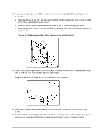
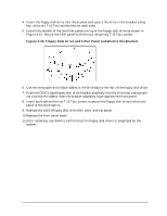
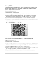
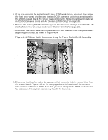
Field Replaceable Units (FRUs) FRU Removal and Replacement 5. Familiarize yourself with the order in which DIMMs must be inserted. This information is on the "Memory Installation Sequence" label on the floor of the workstation's left side. For more details, see the configuration section titled "Memory" on page 39 in Chapter 2. NOTE The J7000 workstation requires that DIMMs are installed in pairs of equal memory size. In contrast, individual DIMMs of different memory sizes (namely, 256 and 512 MB) may be installed in the J5000 workstation. 6. Angle the left and right DIMM extractor handles on the empty DIMM slot outward. 7. Position the DIMM correctly to allow insertion into the DIMM slot. 8. Press firmly and evenly on the DIMM until it is fully seated in the slot. The extractor handles will close inward as the DIMM is inserted. 9. If this is a J7000 workstation, replace the front air divider and the four T-15 Torx screws securing the front air divider. 10.Replace the workstation's top and left side panels. 11.To verify that the DIMM installation was successful, use the Boot Console Handler procedure in "Displaying the Current Monitor Configuration" on page 162 in Chapter 5. 12.If you replaced a faulty DIMM, use the pdt clear command in the Service Menu of the Boot Console Handler. Answer y (yes) to the prompt Continue? (Y/N) >. Chapter 4 107
-
 1
1 -
2
-
3
-
4
-
5
-
6
-
7
-
8
-
9
-
10
-
11
-
12
-
13
-
14
-
15
-
16
-
17
-
18
-
19
-
20
-
21
-
22
-
23
-
24
-
25
-
26
-
27
-
28
-
29
-
30
-
31
-
32
-
33
-
34
-
35
-
36
-
37
-
38
-
39
-
40
-
41
-
42
-
43
-
44
-
45
-
46
-
47
-
48
-
49
-
50
-
51
-
52
-
53
-
54
-
55
-
56
-
57
-
58
-
59
-
60
-
61
-
62
-
63
-
64
-
65
-
66
-
67
-
68
-
69
-
70
-
71
-
72
-
73
-
74
-
75
-
76
-
77
-
78
-
79
-
80
-
81
-
82
-
83
-
84
-
85
-
86
-
87
-
88
-
89
-
90
-
91
-
92
-
93
-
94
-
95
-
96
-
97
-
98
-
99
-
100
-
101
-
102
-
103
-
104
-
105
-
 106
106 -
 107
107 -
 108
108 -
 109
109 -
 110
110 -
 111
111 -
 112
112 -
 113
113 -
 114
114 -
 115
115 -
 116
116 -
117
-
118
-
119
-
120
-
121
-
122
-
123
-
124
-
125
-
126
-
127
-
128
-
129
-
130
-
131
-
132
-
133
-
134
-
135
-
136
-
137
-
138
-
139
-
140
-
141
-
142
-
143
-
144
-
145
-
146
-
147
-
148
-
149
-
150
-
151
-
152
-
153
-
154
-
155
-
156
-
157
-
158
-
159
-
160
-
161
-
162
-
163
-
164
-
165
-
166
-
167
-
168
-
169
-
170
-
171
-
172
-
173
-
174
-
175
-
176
-
177
-
178
-
179
-
180
-
181
-
182
-
183
-
184
-
185
-
186
-
187
-
188
-
189
-
190
-
191
-
192
-
193
-
194
-
195
-
196
-
197
-
198
-
199
-
200
-
201
-
202
-
203
-
204
-
205
-
206
-
207
-
208
-
209
-
210
-
211
-
212
 |
 |