HP Visualize J5000 hp Visualize J5000, J7000 workstations service handbook (a4 - Page 35
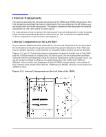
Internal Components on the Left Side of the J7000, System Board, Microprocessors
 |
View all HP Visualize J5000 manuals
Add to My Manuals
Save this manual to your list of manuals |
Page 35 highlights
Product Information Internal Components Figure 1-13. Internal Components on the Left Side of the J7000 J7000 system board } Four PA-8500 microprocessors with turbocoolers DC/DC converter unit Three system board cooling fans DC/DC converter unit Sixteen memory slots System Board The system boards in the J5000 and J7000 contain the PA-8500 microprocessors and memory slots, as well as connectors to other components. Each system board is mounted on a tray, which has a handle. The system board tray assembly is then attached to the workstation by sheet metal hooks in the center wall of the chassis. Over the center wall of the chassis, the system board is attached to the workstation's I/O board by a flex cable and to the power supply by gold plated bus bars. In addition, the system board has connections to the system board fans, which are also located on the left side of the workstation, and to the power switch/LCD assembly, which is on the front panel of the workstation. Microprocessors: You can determine which workstation model it is by counting the microprocessors on the system board. Each microprocessor is cooled by a "turbocooler," which consists of a cylindrical heat sink and an integrated fan. The J5000 has two of these turbocoolers; thus, it has two PA-8500 microprocessors. The J7000 has four turbocoolers; thus, it has four PA-8500 microprocessors. Memory Slots: The J5000 and J7000 workstations also differ in the number of memory slots each has on their system boards, as well as how the slots can be loaded with memory DIMMs. The J5000 has eight memory slots, and memory DIMMs can be installed individually in this workstation. In contrast, the J7000 has sixteen memory slots, and memory DIMMs must be installed in pairs of equal size in it. For more information about the sizes of memory DIMMs each workstation supports, as well as the DIMM loading order for each, see the configuration section for "Memory" on page 39 in Chapter 2. Chapter 1 31
-
 1
1 -
2
-
3
-
4
-
5
-
6
-
7
-
8
-
9
-
10
-
11
-
12
-
13
-
14
-
15
-
16
-
17
-
18
-
19
-
20
-
21
-
22
-
23
-
24
-
25
-
26
-
27
-
28
-
29
-
 30
30 -
 31
31 -
 32
32 -
 33
33 -
 34
34 -
 35
35 -
 36
36 -
 37
37 -
 38
38 -
 39
39 -
 40
40 -
41
-
42
-
43
-
44
-
45
-
46
-
47
-
48
-
49
-
50
-
51
-
52
-
53
-
54
-
55
-
56
-
57
-
58
-
59
-
60
-
61
-
62
-
63
-
64
-
65
-
66
-
67
-
68
-
69
-
70
-
71
-
72
-
73
-
74
-
75
-
76
-
77
-
78
-
79
-
80
-
81
-
82
-
83
-
84
-
85
-
86
-
87
-
88
-
89
-
90
-
91
-
92
-
93
-
94
-
95
-
96
-
97
-
98
-
99
-
100
-
101
-
102
-
103
-
104
-
105
-
106
-
107
-
108
-
109
-
110
-
111
-
112
-
113
-
114
-
115
-
116
-
117
-
118
-
119
-
120
-
121
-
122
-
123
-
124
-
125
-
126
-
127
-
128
-
129
-
130
-
131
-
132
-
133
-
134
-
135
-
136
-
137
-
138
-
139
-
140
-
141
-
142
-
143
-
144
-
145
-
146
-
147
-
148
-
149
-
150
-
151
-
152
-
153
-
154
-
155
-
156
-
157
-
158
-
159
-
160
-
161
-
162
-
163
-
164
-
165
-
166
-
167
-
168
-
169
-
170
-
171
-
172
-
173
-
174
-
175
-
176
-
177
-
178
-
179
-
180
-
181
-
182
-
183
-
184
-
185
-
186
-
187
-
188
-
189
-
190
-
191
-
192
-
193
-
194
-
195
-
196
-
197
-
198
-
199
-
200
-
201
-
202
-
203
-
204
-
205
-
206
-
207
-
208
-
209
-
210
-
211
-
212
 |
 |
