HP Visualize J5000 hp Visualize J5000, J7000 workstations service handbook (a4 - Page 135
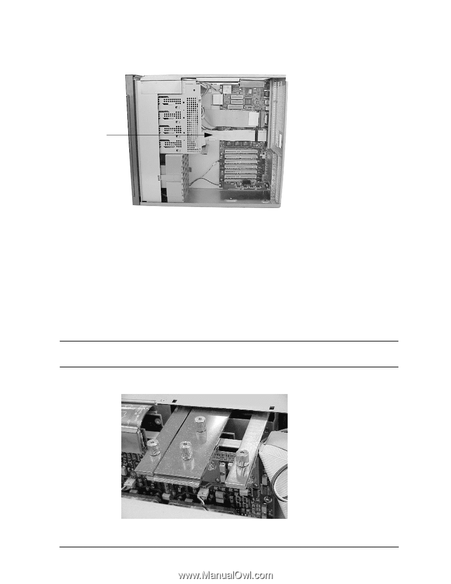
SCSI Cable from the SCA Hard Disk Interface, Bus Bar Thumbscrews
 |
View all HP Visualize J5000 manuals
Add to My Manuals
Save this manual to your list of manuals |
Page 135 highlights
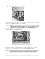
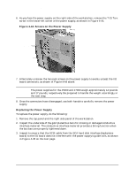
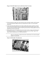
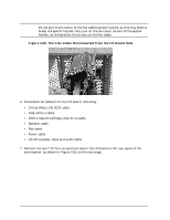
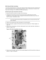
Field Replaceable Units (FRUs) FRU Removal and Replacement Figure 4-45. SCSI Cable from the SCA Hard Disk Interface SCSI cable 4. Pick up the power supply with both hands and align the power supply with the guide rails. Slide the power supply forward on the guide rails to seat it in the I/O board connectors. 5. Insert and alternately tighten the two power supply jack screws, as shown in Figure 4-44 on the previous page. Take care to align the rear face of the power supply to the rear wall of the mainframe chassis so that the jack screws will mate properly. Continue tightening until the screws stop. 6. Secure the bus bars to the system board with either the four bus bar thumbscrews on the J5000 workstation, or the five bus bar thumbscrews on the J7000. Figure 4-46 shows these thumbscrews on the J5000 workstation. NOTE Failure to sufficiently tighten the bus bar thumbscrews will cause the power supply to not activate. Figure 4-46. Bus Bar Thumbscrews Chapter 4 131
-
 1
1 -
2
-
3
-
4
-
5
-
6
-
7
-
8
-
9
-
10
-
11
-
12
-
13
-
14
-
15
-
16
-
17
-
18
-
19
-
20
-
21
-
22
-
23
-
24
-
25
-
26
-
27
-
28
-
29
-
30
-
31
-
32
-
33
-
34
-
35
-
36
-
37
-
38
-
39
-
40
-
41
-
42
-
43
-
44
-
45
-
46
-
47
-
48
-
49
-
50
-
51
-
52
-
53
-
54
-
55
-
56
-
57
-
58
-
59
-
60
-
61
-
62
-
63
-
64
-
65
-
66
-
67
-
68
-
69
-
70
-
71
-
72
-
73
-
74
-
75
-
76
-
77
-
78
-
79
-
80
-
81
-
82
-
83
-
84
-
85
-
86
-
87
-
88
-
89
-
90
-
91
-
92
-
93
-
94
-
95
-
96
-
97
-
98
-
99
-
100
-
101
-
102
-
103
-
104
-
105
-
106
-
107
-
108
-
109
-
110
-
111
-
112
-
113
-
114
-
115
-
116
-
117
-
118
-
119
-
120
-
121
-
122
-
123
-
124
-
125
-
126
-
127
-
128
-
129
-
 130
130 -
 131
131 -
 132
132 -
 133
133 -
 134
134 -
 135
135 -
 136
136 -
 137
137 -
 138
138 -
 139
139 -
 140
140 -
141
-
142
-
143
-
144
-
145
-
146
-
147
-
148
-
149
-
150
-
151
-
152
-
153
-
154
-
155
-
156
-
157
-
158
-
159
-
160
-
161
-
162
-
163
-
164
-
165
-
166
-
167
-
168
-
169
-
170
-
171
-
172
-
173
-
174
-
175
-
176
-
177
-
178
-
179
-
180
-
181
-
182
-
183
-
184
-
185
-
186
-
187
-
188
-
189
-
190
-
191
-
192
-
193
-
194
-
195
-
196
-
197
-
198
-
199
-
200
-
201
-
202
-
203
-
204
-
205
-
206
-
207
-
208
-
209
-
210
-
211
-
212
 |
 |