HP Visualize J5000 hp Visualize J5000, J7000 workstations service handbook (a4 - Page 98
Removing the Side Panels, Replacing the Top and Side Panels
 |
View all HP Visualize J5000 manuals
Add to My Manuals
Save this manual to your list of manuals |
Page 98 highlights
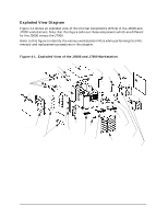
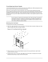
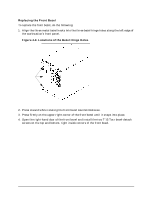
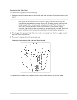
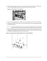
Field Replaceable Units (FRUs) FRU Removal and Replacement Removing the Side Panels To remove one or both of the side panels, do the following: 1. Remove the top panel, as explained in the previous procedure. 2. Remove each side panel by tipping it out and away from the workstation, as shown in Figure 4-4 on the previous page. To replace the side panels, see "Replacing the Top and Side Panels" below. Replacing the Top and Side Panels To replace the top and side panels, do the following: 1. Place each side panel into the groove in the bottom edge of the workstation's side, and then press the top of the each side panel into the top edge of the workstation's side. 2. Place the top panel on the top of the workstation, with about an inch of its back edge protruding over the workstation's rear panel. Then push the top panel straight forward, so its front edge slides underneath the lip of the front panel's top edge. The top panel fits snugly, so you may have to get a firm grip on it in order to slide it into place. 3. Screw the two thumbscrews into the tabs in the upper corners of the rear panel. Note that the upper-left thumbscrew is the power supply interlock screw; so be sure that it is firmly retightened, or the power supply may not engage. 94 Chapter 4
-
 1
1 -
2
-
3
-
4
-
5
-
6
-
7
-
8
-
9
-
10
-
11
-
12
-
13
-
14
-
15
-
16
-
17
-
18
-
19
-
20
-
21
-
22
-
23
-
24
-
25
-
26
-
27
-
28
-
29
-
30
-
31
-
32
-
33
-
34
-
35
-
36
-
37
-
38
-
39
-
40
-
41
-
42
-
43
-
44
-
45
-
46
-
47
-
48
-
49
-
50
-
51
-
52
-
53
-
54
-
55
-
56
-
57
-
58
-
59
-
60
-
61
-
62
-
63
-
64
-
65
-
66
-
67
-
68
-
69
-
70
-
71
-
72
-
73
-
74
-
75
-
76
-
77
-
78
-
79
-
80
-
81
-
82
-
83
-
84
-
85
-
86
-
87
-
88
-
89
-
90
-
91
-
92
-
 93
93 -
 94
94 -
 95
95 -
 96
96 -
 97
97 -
 98
98 -
 99
99 -
 100
100 -
 101
101 -
 102
102 -
 103
103 -
104
-
105
-
106
-
107
-
108
-
109
-
110
-
111
-
112
-
113
-
114
-
115
-
116
-
117
-
118
-
119
-
120
-
121
-
122
-
123
-
124
-
125
-
126
-
127
-
128
-
129
-
130
-
131
-
132
-
133
-
134
-
135
-
136
-
137
-
138
-
139
-
140
-
141
-
142
-
143
-
144
-
145
-
146
-
147
-
148
-
149
-
150
-
151
-
152
-
153
-
154
-
155
-
156
-
157
-
158
-
159
-
160
-
161
-
162
-
163
-
164
-
165
-
166
-
167
-
168
-
169
-
170
-
171
-
172
-
173
-
174
-
175
-
176
-
177
-
178
-
179
-
180
-
181
-
182
-
183
-
184
-
185
-
186
-
187
-
188
-
189
-
190
-
191
-
192
-
193
-
194
-
195
-
196
-
197
-
198
-
199
-
200
-
201
-
202
-
203
-
204
-
205
-
206
-
207
-
208
-
209
-
210
-
211
-
212
 |
 |