HP Visualize J5000 hp Visualize J5000, J7000 workstations service handbook (a4 - Page 120
procedures in DC/DC Converter Units and Air Dividers J7000 Only
 |
View all HP Visualize J5000 manuals
Add to My Manuals
Save this manual to your list of manuals |
Page 120 highlights
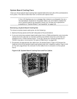
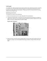
Field Replaceable Units (FRUs) FRU Removal and Replacement 11.Replace the memory DIMMs in the system board by following the replacement procedures in "Memory DIMMs" on page 106. 12.If you are replacing the system board in a J7000 workstation, you must also replace the two DC/DC converter units that are attached to the J7000's system board, as well as the front and rear air dividers. To replace these components, follow the replacement procedures in "DC/DC Converter Units and Air Dividers (J7000 Only)" on page 108. 13.Replace the top panel and the left side panel of the workstation. 116 Chapter 4
-
 1
1 -
2
-
3
-
4
-
5
-
6
-
7
-
8
-
9
-
10
-
11
-
12
-
13
-
14
-
15
-
16
-
17
-
18
-
19
-
20
-
21
-
22
-
23
-
24
-
25
-
26
-
27
-
28
-
29
-
30
-
31
-
32
-
33
-
34
-
35
-
36
-
37
-
38
-
39
-
40
-
41
-
42
-
43
-
44
-
45
-
46
-
47
-
48
-
49
-
50
-
51
-
52
-
53
-
54
-
55
-
56
-
57
-
58
-
59
-
60
-
61
-
62
-
63
-
64
-
65
-
66
-
67
-
68
-
69
-
70
-
71
-
72
-
73
-
74
-
75
-
76
-
77
-
78
-
79
-
80
-
81
-
82
-
83
-
84
-
85
-
86
-
87
-
88
-
89
-
90
-
91
-
92
-
93
-
94
-
95
-
96
-
97
-
98
-
99
-
100
-
101
-
102
-
103
-
104
-
105
-
106
-
107
-
108
-
109
-
110
-
111
-
112
-
113
-
114
-
 115
115 -
 116
116 -
 117
117 -
 118
118 -
 119
119 -
 120
120 -
 121
121 -
 122
122 -
 123
123 -
 124
124 -
 125
125 -
126
-
127
-
128
-
129
-
130
-
131
-
132
-
133
-
134
-
135
-
136
-
137
-
138
-
139
-
140
-
141
-
142
-
143
-
144
-
145
-
146
-
147
-
148
-
149
-
150
-
151
-
152
-
153
-
154
-
155
-
156
-
157
-
158
-
159
-
160
-
161
-
162
-
163
-
164
-
165
-
166
-
167
-
168
-
169
-
170
-
171
-
172
-
173
-
174
-
175
-
176
-
177
-
178
-
179
-
180
-
181
-
182
-
183
-
184
-
185
-
186
-
187
-
188
-
189
-
190
-
191
-
192
-
193
-
194
-
195
-
196
-
197
-
198
-
199
-
200
-
201
-
202
-
203
-
204
-
205
-
206
-
207
-
208
-
209
-
210
-
211
-
212
 |
 |

116
Chapter 4
Field Replaceable Units (FRUs)
FRU Removal and Replacement
11.Replace the memory DIMMs in the system board by following the replacement
procedures in “Memory DIMMs” on page 106.
12.If you are replacing the system board in a J7000 workstation, you must also replace the
two DC/DC converter units that are attached to the J7000’s system board, as well as the
front and rear air dividers. To replace these components, follow the replacement
procedures in “DC/DC Converter Units and Air Dividers (J7000 Only)” on page 108.
13.Replace the top panel and the left side panel of the workstation.