HP Visualize J5000 hp Visualize J5000, J7000 workstations service handbook (a4 - Page 28
Rear Panel Components, Components on the Rear Panel
 |
View all HP Visualize J5000 manuals
Add to My Manuals
Save this manual to your list of manuals |
Page 28 highlights
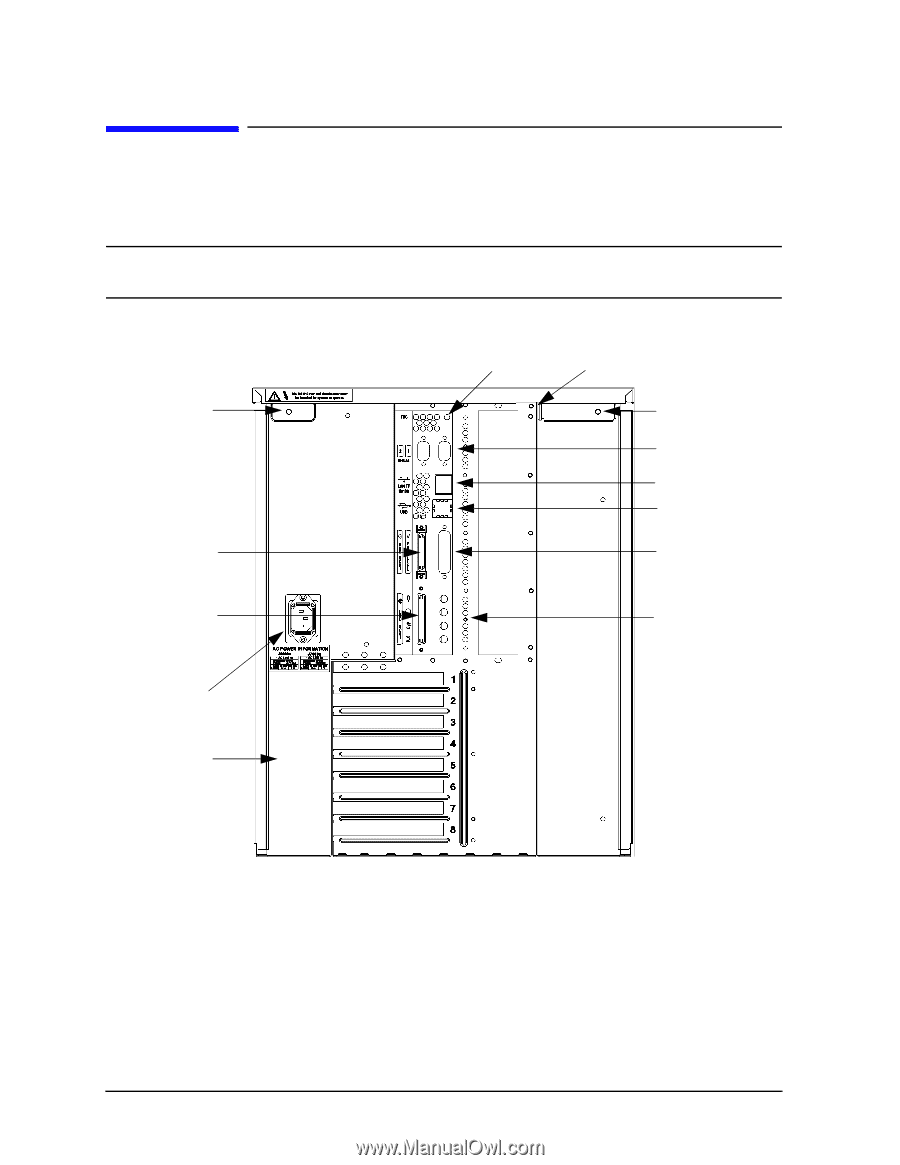
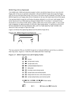
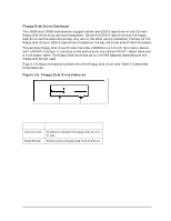
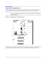
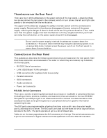
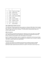
Product Information Rear Panel Components Rear Panel Components This section describes the various components located on the rear panel of the J5000 and J7000 workstations. Figure 1-9 shows the locations of these rear panel components. NOTE To maintain FCC/EMI compliance, verify that all cables are fully seated and properly fastened. Figure 1-9. Components on the Rear Panel Power supply interlock thumbscrew (Torx T-15) NSE SCSI-2 connector Ultra2 Wide LVD SCSI connector Power cord connector I/O slots { TOC button Security tab Thumbscrew (T-15) Two RS-232C Serial connectors LAN 10/100 BaseT RJ45 connector Two USB connectors Parallel connector } Audio connectors: Microphone In Headphones Out Line Out Line In The following three subsections describe the thumbscrews, connectors, and miscellaneous components that are located on the rear panel of the J5000 and J7000 workstations. 24 Chapter 1
-
 1
1 -
2
-
3
-
4
-
5
-
6
-
7
-
8
-
9
-
10
-
11
-
12
-
13
-
14
-
15
-
16
-
17
-
18
-
19
-
20
-
21
-
22
-
 23
23 -
 24
24 -
 25
25 -
 26
26 -
 27
27 -
 28
28 -
 29
29 -
 30
30 -
 31
31 -
 32
32 -
 33
33 -
34
-
35
-
36
-
37
-
38
-
39
-
40
-
41
-
42
-
43
-
44
-
45
-
46
-
47
-
48
-
49
-
50
-
51
-
52
-
53
-
54
-
55
-
56
-
57
-
58
-
59
-
60
-
61
-
62
-
63
-
64
-
65
-
66
-
67
-
68
-
69
-
70
-
71
-
72
-
73
-
74
-
75
-
76
-
77
-
78
-
79
-
80
-
81
-
82
-
83
-
84
-
85
-
86
-
87
-
88
-
89
-
90
-
91
-
92
-
93
-
94
-
95
-
96
-
97
-
98
-
99
-
100
-
101
-
102
-
103
-
104
-
105
-
106
-
107
-
108
-
109
-
110
-
111
-
112
-
113
-
114
-
115
-
116
-
117
-
118
-
119
-
120
-
121
-
122
-
123
-
124
-
125
-
126
-
127
-
128
-
129
-
130
-
131
-
132
-
133
-
134
-
135
-
136
-
137
-
138
-
139
-
140
-
141
-
142
-
143
-
144
-
145
-
146
-
147
-
148
-
149
-
150
-
151
-
152
-
153
-
154
-
155
-
156
-
157
-
158
-
159
-
160
-
161
-
162
-
163
-
164
-
165
-
166
-
167
-
168
-
169
-
170
-
171
-
172
-
173
-
174
-
175
-
176
-
177
-
178
-
179
-
180
-
181
-
182
-
183
-
184
-
185
-
186
-
187
-
188
-
189
-
190
-
191
-
192
-
193
-
194
-
195
-
196
-
197
-
198
-
199
-
200
-
201
-
202
-
203
-
204
-
205
-
206
-
207
-
208
-
209
-
210
-
211
-
212
 |
 |