HP Visualize J5000 hp Visualize J5000, J7000 workstations service handbook (a4 - Page 118
Replacing the System Board Tray Assembly, Connecting the Flex Cable
 |
View all HP Visualize J5000 manuals
Add to My Manuals
Save this manual to your list of manuals |
Page 118 highlights
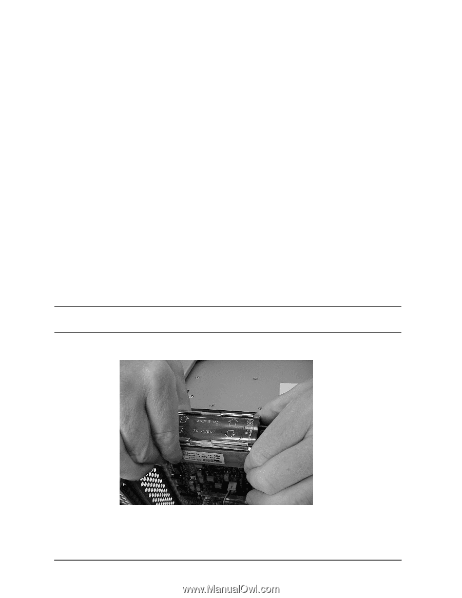
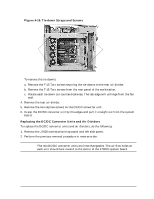
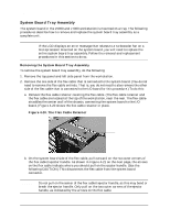
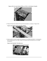
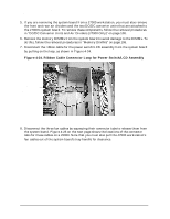
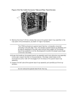
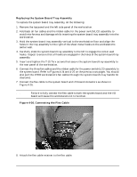
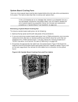
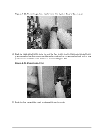
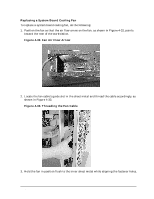
Field Replaceable Units (FRUs) FRU Removal and Replacement Replacing the System Board Tray Assembly To replace the system board tray assembly, do the following: 1. Remove the top panel and the left side panel of the workstation. 2. Fold back all fan cables and the ribbon cable for the power switch/LCD assembly to avoid interference and damage while inserting the system board tray assembly into the workstation. 3. Hold the system board tray assembly vertical to the workstation floor and align the holes in the tray assembly to the right of the sheet metal hooks on the workstation's center wall. 4. Carefully slide the system board tray assembly to the left to engage the center wall hooks. Inspect to ensure that all hooks are engaged in the holes of the system board tray assembly. 5. Insert and tighten the T-15 Torx screws that secure the system board tray assembly to the rear panel of the workstation. 6. Connect the three fan cables and the ribbon cable for the power switch/LCD assembly to the system board. Refer to Figures 4-24 and 4-25 on the previous two pages. You should also pull the J7000 workstation's fan cables through the system board's tray handle for clearance. 7. Connect the flex cable to the system board and I/O board connectors as shown in Figure 4-26. NOTE Failure to fully connect the flex cable to both the system board and the I/O board will cause the workstation not to function. Figure 4-26. Connecting the Flex Cable 8. Attach the flex cable retainer to the flex cable. 114 Chapter 4
-
 1
1 -
2
-
3
-
4
-
5
-
6
-
7
-
8
-
9
-
10
-
11
-
12
-
13
-
14
-
15
-
16
-
17
-
18
-
19
-
20
-
21
-
22
-
23
-
24
-
25
-
26
-
27
-
28
-
29
-
30
-
31
-
32
-
33
-
34
-
35
-
36
-
37
-
38
-
39
-
40
-
41
-
42
-
43
-
44
-
45
-
46
-
47
-
48
-
49
-
50
-
51
-
52
-
53
-
54
-
55
-
56
-
57
-
58
-
59
-
60
-
61
-
62
-
63
-
64
-
65
-
66
-
67
-
68
-
69
-
70
-
71
-
72
-
73
-
74
-
75
-
76
-
77
-
78
-
79
-
80
-
81
-
82
-
83
-
84
-
85
-
86
-
87
-
88
-
89
-
90
-
91
-
92
-
93
-
94
-
95
-
96
-
97
-
98
-
99
-
100
-
101
-
102
-
103
-
104
-
105
-
106
-
107
-
108
-
109
-
110
-
111
-
112
-
 113
113 -
 114
114 -
 115
115 -
 116
116 -
 117
117 -
 118
118 -
 119
119 -
 120
120 -
 121
121 -
 122
122 -
 123
123 -
124
-
125
-
126
-
127
-
128
-
129
-
130
-
131
-
132
-
133
-
134
-
135
-
136
-
137
-
138
-
139
-
140
-
141
-
142
-
143
-
144
-
145
-
146
-
147
-
148
-
149
-
150
-
151
-
152
-
153
-
154
-
155
-
156
-
157
-
158
-
159
-
160
-
161
-
162
-
163
-
164
-
165
-
166
-
167
-
168
-
169
-
170
-
171
-
172
-
173
-
174
-
175
-
176
-
177
-
178
-
179
-
180
-
181
-
182
-
183
-
184
-
185
-
186
-
187
-
188
-
189
-
190
-
191
-
192
-
193
-
194
-
195
-
196
-
197
-
198
-
199
-
200
-
201
-
202
-
203
-
204
-
205
-
206
-
207
-
208
-
209
-
210
-
211
-
212
 |
 |