HP Visualize J5000 hp Visualize J5000, J7000 workstations service handbook (a4 - Page 208
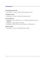
Manuals related to J5000/J7000, in Boot Console Handler
 |
View all HP Visualize J5000 manuals
Add to My Manuals
Save this manual to your list of manuals |
Page 208 highlights
Index electrical specifications, 179 environmental specifications, 178 ESD precautions, 88 exploded view diagram, 90 fan problems, 80 features, 15 floppy disk drive, 23, 104 floppy disk drive configuration, 39 flowcharts for troubleshooting, 47 front panel bezel, 18, 91 front panel components, 17 FRUs, 81 graphics cards supported, 16 hard disk drive configuration, 36 hard disk drives, 20, 96 I/O board, 33, 133 I/O card configuration, 42 I/O cards, 121 I/O cooling fan, 33, 138 I/O slots, 16, 29 internal components on left side, 30 internal components on right side, 32 internal storage devices, 15, 20, 96 ISL environment, 53, 173 keyboard, 34 LCD, 20, 95 LCD-indicated conditions, 54 lifting ledge, 17, 89 memory DIMMs, 106 memory failures, 54 memory slots, 15, 31 microprocessors, 31 monitor configuration, 43 monitors supported, 34 mouse, 34 net weights, 14 networking, 15 ODE-based diagnostics, 79 operating system versions, 15 panels, 93, 94 part numbers for FRUs, 83 physical dimensions, 14 ports, 15 power requirements, 179 power supply, 15, 33, 128 power switch, 19, 95 powering off, 19, 89 product description, 14 real-time clock module, 125 rear panel components, 24 regulatory requirements, 182 regulatory statements, 182 related documentation, 200 resetting, 158 safety statements, 182 SCA hard disk interface, 33, 136 security tab, 29 selftest failures, 54 side panels, 94 speaker, 33, 142 stable storage, 52 Support Tools Manager, 78 system board, 31, 110 system board cooling fans, 32, 117 system verification tests, 78 thumbscrews on rear panel, 25 TOC button, 29 tools required for FRUs, 83 top panel, 93, 94 troubleshooting, 45 user interface, 15 J7000 workstation air dividers, 32 DC/DC converter units, 32, 108 DIMM loading order, 40 internal components on left side, 31 memory configuration, 40 memory DIMMs, 107 memory slots, 15, 31 microprocessors, 15, 31 net weight, 14 power cord connector, 28 power supply, 15, 33, 128 site preparation guide, 34, 200 K Keyboard supported, 34 L LAN connector, 26 LAN station address, displaying in Boot Console Handler, 171 lanaddress command in Boot Console Handler, 171 LCD chassis codes, 54, 55 description of, 20 FRU removal/replacement, 95 symbols, 20 LCD-indicated conditions, troubleshooting, 54 LED codes for DDS-3 tape drive, 22 Lifting ledge, 17, 89 Loading order of DIMMs in J5000, 39 in J7000, 40 M Main troubleshooting flowchart, 47 Manuals related to J5000/J7000, 200 204 Index
-
 1
1 -
2
-
3
-
4
-
5
-
6
-
7
-
8
-
9
-
10
-
11
-
12
-
13
-
14
-
15
-
16
-
17
-
18
-
19
-
20
-
21
-
22
-
23
-
24
-
25
-
26
-
27
-
28
-
29
-
30
-
31
-
32
-
33
-
34
-
35
-
36
-
37
-
38
-
39
-
40
-
41
-
42
-
43
-
44
-
45
-
46
-
47
-
48
-
49
-
50
-
51
-
52
-
53
-
54
-
55
-
56
-
57
-
58
-
59
-
60
-
61
-
62
-
63
-
64
-
65
-
66
-
67
-
68
-
69
-
70
-
71
-
72
-
73
-
74
-
75
-
76
-
77
-
78
-
79
-
80
-
81
-
82
-
83
-
84
-
85
-
86
-
87
-
88
-
89
-
90
-
91
-
92
-
93
-
94
-
95
-
96
-
97
-
98
-
99
-
100
-
101
-
102
-
103
-
104
-
105
-
106
-
107
-
108
-
109
-
110
-
111
-
112
-
113
-
114
-
115
-
116
-
117
-
118
-
119
-
120
-
121
-
122
-
123
-
124
-
125
-
126
-
127
-
128
-
129
-
130
-
131
-
132
-
133
-
134
-
135
-
136
-
137
-
138
-
139
-
140
-
141
-
142
-
143
-
144
-
145
-
146
-
147
-
148
-
149
-
150
-
151
-
152
-
153
-
154
-
155
-
156
-
157
-
158
-
159
-
160
-
161
-
162
-
163
-
164
-
165
-
166
-
167
-
168
-
169
-
170
-
171
-
172
-
173
-
174
-
175
-
176
-
177
-
178
-
179
-
180
-
181
-
182
-
183
-
184
-
185
-
186
-
187
-
188
-
189
-
190
-
191
-
192
-
193
-
194
-
195
-
196
-
197
-
198
-
199
-
200
-
201
-
202
-
 203
203 -
 204
204 -
 205
205 -
 206
206 -
 207
207 -
 208
208 -
 209
209 -
 210
210 -
 211
211 -
 212
212
 |
 |