HP Visualize J5000 hp Visualize J5000, J7000 workstations service handbook (a4 - Page 24
System LCD, Internal Storage Devices, LCD Symbols, Hard Disk Drives
 |
View all HP Visualize J5000 manuals
Add to My Manuals
Save this manual to your list of manuals |
Page 24 highlights
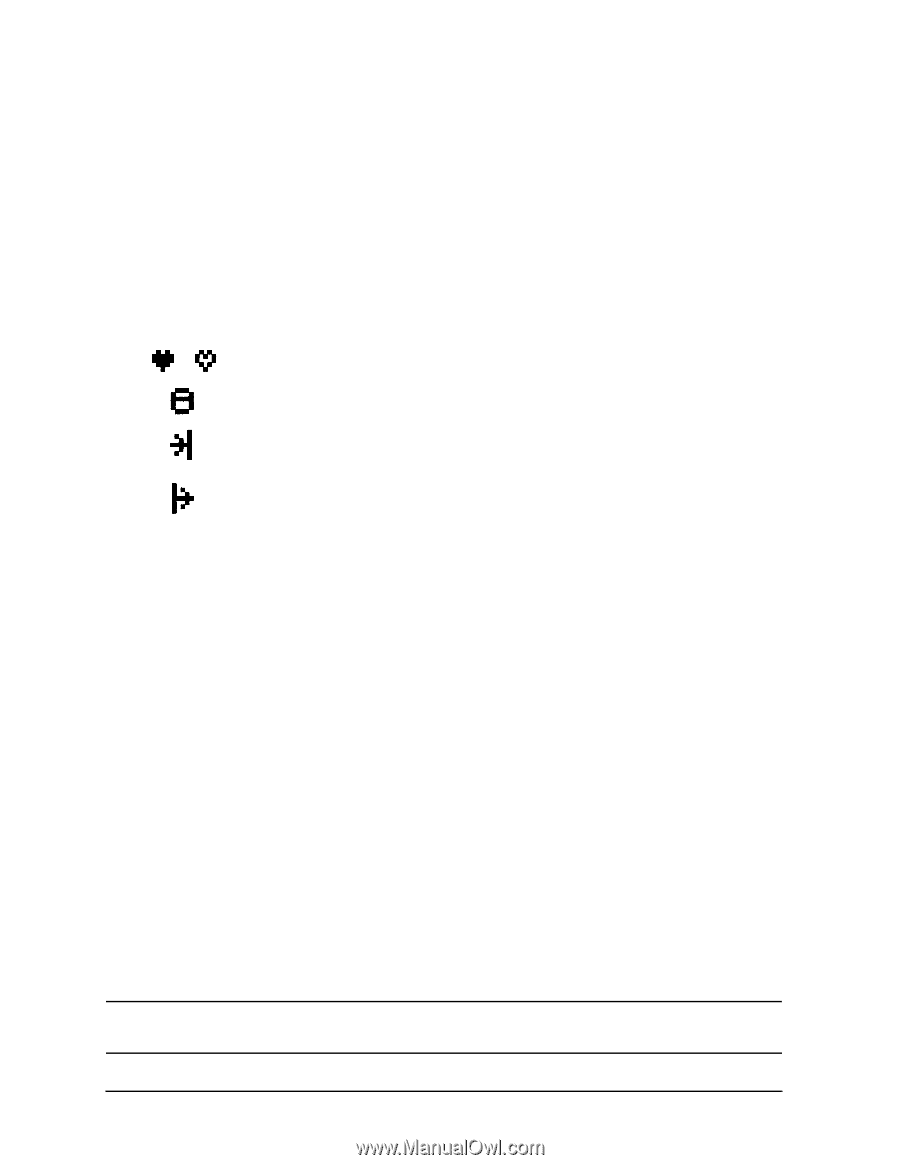
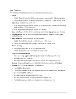
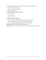
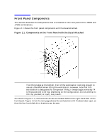
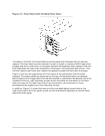
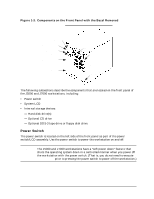
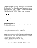
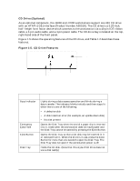
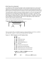
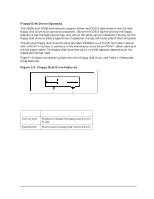
Product Information Front Panel Components System LCD The Liquid Crystal Display (LCD) indicator is located on the left side of the front panel as part of the power switch/LCD assembly. The LCD lights when the workstation power is on. The LCD has a 2-line display, with up to 16-characters per line. It displays messages about the state of the system, which are called chassis codes. See the section titled "Identifying LCD-Indicated Conditions" on page 54 in Chapter 3 for a complete listing of the possible chassis codes which can be displayed on the LCD. The following symbols appear in the LCD, representing different system activities. Figure 1-4. LCD Symbols Operating system running Disk access in progress Network Receive in progress Network Transmit in progress Internal Storage Devices The J5000 and J7000 workstations support the following internal storage devices, which are also located on the front panel: • Up to four hot-pluggable, SCA (Single Connector Attach) hard disk drives • Optionally, one 32X CD drive • Optionally, either one DDS-3 tape drive, or one 3.5-inch floppy disk drive The following subsections describe these internal storage devices. Hard Disk Drive(s) The J5000 and J7000 workstations can support up to four hot-pluggable, SCA (Single Connector Attach) hard disk drives. These hard disk drives are 3.5-inch form factor, 10K RPM devices which connect to Ultra2 Wide LVD (Low Voltage Differential) SCSI interfaces on the disk bay backplane. The hard disk drive bays are located behind the right-hand door of the bezel that is attached to the workstation's front panel. The two hard disk drive models currently supported are: • 9 GB LVD 10K RPM disk drive (Product Number A4997A) • 18 GB LVD 10K RPM disk drive (Product Number A4998A) NOTE The ability to hot plug the hard disk drive(s) requires MirrorDisk/UX (Product Number B5403BA on HP-UX 10.20, or B2491BA on HP-UX 11.0). 20 Chapter 1
-
 1
1 -
2
-
3
-
4
-
5
-
6
-
7
-
8
-
9
-
10
-
11
-
12
-
13
-
14
-
15
-
16
-
17
-
18
-
 19
19 -
 20
20 -
 21
21 -
 22
22 -
 23
23 -
 24
24 -
 25
25 -
 26
26 -
 27
27 -
 28
28 -
 29
29 -
30
-
31
-
32
-
33
-
34
-
35
-
36
-
37
-
38
-
39
-
40
-
41
-
42
-
43
-
44
-
45
-
46
-
47
-
48
-
49
-
50
-
51
-
52
-
53
-
54
-
55
-
56
-
57
-
58
-
59
-
60
-
61
-
62
-
63
-
64
-
65
-
66
-
67
-
68
-
69
-
70
-
71
-
72
-
73
-
74
-
75
-
76
-
77
-
78
-
79
-
80
-
81
-
82
-
83
-
84
-
85
-
86
-
87
-
88
-
89
-
90
-
91
-
92
-
93
-
94
-
95
-
96
-
97
-
98
-
99
-
100
-
101
-
102
-
103
-
104
-
105
-
106
-
107
-
108
-
109
-
110
-
111
-
112
-
113
-
114
-
115
-
116
-
117
-
118
-
119
-
120
-
121
-
122
-
123
-
124
-
125
-
126
-
127
-
128
-
129
-
130
-
131
-
132
-
133
-
134
-
135
-
136
-
137
-
138
-
139
-
140
-
141
-
142
-
143
-
144
-
145
-
146
-
147
-
148
-
149
-
150
-
151
-
152
-
153
-
154
-
155
-
156
-
157
-
158
-
159
-
160
-
161
-
162
-
163
-
164
-
165
-
166
-
167
-
168
-
169
-
170
-
171
-
172
-
173
-
174
-
175
-
176
-
177
-
178
-
179
-
180
-
181
-
182
-
183
-
184
-
185
-
186
-
187
-
188
-
189
-
190
-
191
-
192
-
193
-
194
-
195
-
196
-
197
-
198
-
199
-
200
-
201
-
202
-
203
-
204
-
205
-
206
-
207
-
208
-
209
-
210
-
211
-
212
 |
 |