HP Visualize J5000 hp Visualize J5000, J7000 workstations service handbook (a4 - Page 58
Identifying LCD-Indicated Conditions, Selftest Failures, Memory Failures
 |
View all HP Visualize J5000 manuals
Add to My Manuals
Save this manual to your list of manuals |
Page 58 highlights
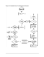
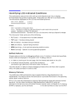
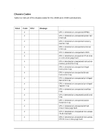
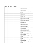
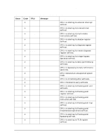
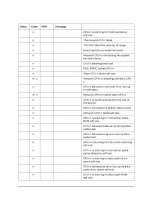
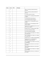
Troubleshooting Identifying LCD-Indicated Conditions Identifying LCD-Indicated Conditions This workstation uses a 2-line LCD, with up to 16-characters per line, to display firmware/operating system progress codes. These codes are referred to as chassis codes. The information displayed on the LCD has the following format: XXX YYYY: ZZZZZZ (Line 1) AAAAAAAAAAAAAAAA (Line 2) Where: XXX - represents a 3-character Ostat YYYY - represents a 4-digit hex code identifying the code module being executed ZZZZZZ - represents a 6-digit FRU descriptor AAAAAAAAAAAAAAAA - represents text (up to 16 characters) relating a diagnostic message The 3-character Ostat can be one of the following: • FLT (fault) - A hardware error has been detected • TST (test) - Hardware being tested • INI (initialize) - Hardware being initialized • SHU (shutdown) - System being shutdown • WRN (warning) - A non-optimal operating condition exists • RUN (running) - System is running operating system Selftest Failures Chassis codes are the key to debugging selftest errors. If a failure is found during selftest, chassis codes are displayed in the system LCD. To debug a failure: 1. In Table 3-1 starting on the next page, find the chassis code listed on the LCD. 2. In the Boot Console Handler, use the Service Menu's pim, pdt, and ChassisCodes commands to get additional information about the failure. The FRU column in Table 3-1 shows messages printed on the LCD that refer to system FRUs. All codes are listed in numeric order. Memory Failures The J5000 and J7000 workstations require special Memory Page Deallocation to be implemented. This feature allows the workstation to provide information to the operating system about memory failures. HP-UX 10.x uses this information to map out failing memory areas and continue normal operation. You can check the Memory Page Deallocation Table (PDT) using the pdt command in the Service menu of the Boot Console Handler (refer to Chapter 5). If a failing DIMM is replaced, use the command pdt clear in the Service Menu to clear out the PDT. 54 Chapter 3
-
 1
1 -
2
-
3
-
4
-
5
-
6
-
7
-
8
-
9
-
10
-
11
-
12
-
13
-
14
-
15
-
16
-
17
-
18
-
19
-
20
-
21
-
22
-
23
-
24
-
25
-
26
-
27
-
28
-
29
-
30
-
31
-
32
-
33
-
34
-
35
-
36
-
37
-
38
-
39
-
40
-
41
-
42
-
43
-
44
-
45
-
46
-
47
-
48
-
49
-
50
-
51
-
52
-
 53
53 -
 54
54 -
 55
55 -
 56
56 -
 57
57 -
 58
58 -
 59
59 -
 60
60 -
 61
61 -
 62
62 -
 63
63 -
64
-
65
-
66
-
67
-
68
-
69
-
70
-
71
-
72
-
73
-
74
-
75
-
76
-
77
-
78
-
79
-
80
-
81
-
82
-
83
-
84
-
85
-
86
-
87
-
88
-
89
-
90
-
91
-
92
-
93
-
94
-
95
-
96
-
97
-
98
-
99
-
100
-
101
-
102
-
103
-
104
-
105
-
106
-
107
-
108
-
109
-
110
-
111
-
112
-
113
-
114
-
115
-
116
-
117
-
118
-
119
-
120
-
121
-
122
-
123
-
124
-
125
-
126
-
127
-
128
-
129
-
130
-
131
-
132
-
133
-
134
-
135
-
136
-
137
-
138
-
139
-
140
-
141
-
142
-
143
-
144
-
145
-
146
-
147
-
148
-
149
-
150
-
151
-
152
-
153
-
154
-
155
-
156
-
157
-
158
-
159
-
160
-
161
-
162
-
163
-
164
-
165
-
166
-
167
-
168
-
169
-
170
-
171
-
172
-
173
-
174
-
175
-
176
-
177
-
178
-
179
-
180
-
181
-
182
-
183
-
184
-
185
-
186
-
187
-
188
-
189
-
190
-
191
-
192
-
193
-
194
-
195
-
196
-
197
-
198
-
199
-
200
-
201
-
202
-
203
-
204
-
205
-
206
-
207
-
208
-
209
-
210
-
211
-
212
 |
 |