HP Visualize J5000 hp Visualize J5000, J7000 workstations service handbook (a4 - Page 94
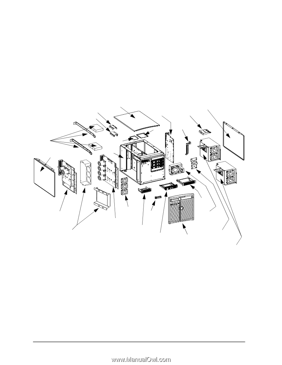
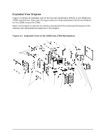
Exploded View Diagram, Exploded View of the J5000 and J7000 Workstation
 |
View all HP Visualize J5000 manuals
Add to My Manuals
Save this manual to your list of manuals |
Page 94 highlights
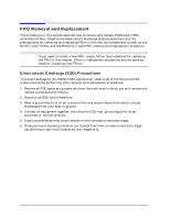
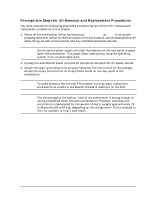
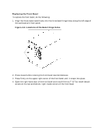
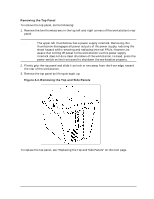
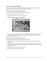
Field Replaceable Units (FRUs) FRU Removal and Replacement Exploded View Diagram Figure 4-1 shows an exploded view of the internal components (FRUs) in the J5000 and J7000 workstations. Note that this figure calls-out those components which are different for the J5000 versus the J7000. Refer to this figure to identify the various workstation FRUs while performing the FRU removal and replacement procedures in this chapter. Figure 4-1. Exploded View of the J5000 and J7000 Workstation Flex cable Top panel retainer Flex cable DC/DC converter units and tie-downs for J7000 Left side panel DDS-3/floppy EMI cover Chassis I/O board CD EMI cover Right side panel Bus bar shield PCI retainer clip J5000 system board tray assembly Rear and front air dividers for J7000 System board cooling fans Power switch/ J7000 system board LCD tray assembly DDS-3/floppy drive bracket Hard disk drive bracket CD drive bracket I/O cooling fan and speaker Front bezel SCA hard disk interface Power supply for J7000 (top) and J5000 (bottom) 90 Chapter 4
-
 1
1 -
2
-
3
-
4
-
5
-
6
-
7
-
8
-
9
-
10
-
11
-
12
-
13
-
14
-
15
-
16
-
17
-
18
-
19
-
20
-
21
-
22
-
23
-
24
-
25
-
26
-
27
-
28
-
29
-
30
-
31
-
32
-
33
-
34
-
35
-
36
-
37
-
38
-
39
-
40
-
41
-
42
-
43
-
44
-
45
-
46
-
47
-
48
-
49
-
50
-
51
-
52
-
53
-
54
-
55
-
56
-
57
-
58
-
59
-
60
-
61
-
62
-
63
-
64
-
65
-
66
-
67
-
68
-
69
-
70
-
71
-
72
-
73
-
74
-
75
-
76
-
77
-
78
-
79
-
80
-
81
-
82
-
83
-
84
-
85
-
86
-
87
-
88
-
 89
89 -
 90
90 -
 91
91 -
 92
92 -
 93
93 -
 94
94 -
 95
95 -
 96
96 -
 97
97 -
 98
98 -
 99
99 -
100
-
101
-
102
-
103
-
104
-
105
-
106
-
107
-
108
-
109
-
110
-
111
-
112
-
113
-
114
-
115
-
116
-
117
-
118
-
119
-
120
-
121
-
122
-
123
-
124
-
125
-
126
-
127
-
128
-
129
-
130
-
131
-
132
-
133
-
134
-
135
-
136
-
137
-
138
-
139
-
140
-
141
-
142
-
143
-
144
-
145
-
146
-
147
-
148
-
149
-
150
-
151
-
152
-
153
-
154
-
155
-
156
-
157
-
158
-
159
-
160
-
161
-
162
-
163
-
164
-
165
-
166
-
167
-
168
-
169
-
170
-
171
-
172
-
173
-
174
-
175
-
176
-
177
-
178
-
179
-
180
-
181
-
182
-
183
-
184
-
185
-
186
-
187
-
188
-
189
-
190
-
191
-
192
-
193
-
194
-
195
-
196
-
197
-
198
-
199
-
200
-
201
-
202
-
203
-
204
-
205
-
206
-
207
-
208
-
209
-
210
-
211
-
212
 |
 |