HP Visualize J5000 hp Visualize J5000, J7000 workstations service handbook (a4 - Page 134
Screws on the Power Supply, Replacing the Power Supply, do the following
 |
View all HP Visualize J5000 manuals
Add to My Manuals
Save this manual to your list of manuals |
Page 134 highlights
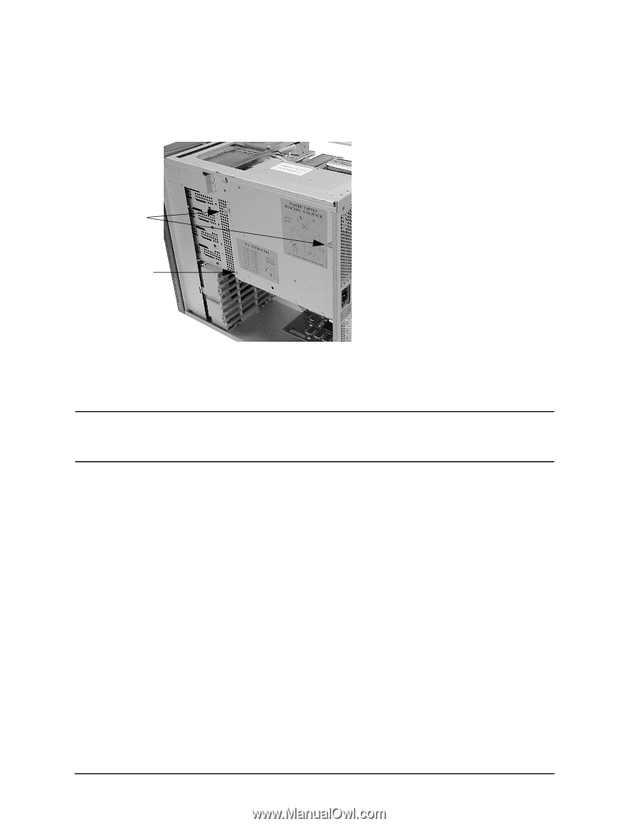
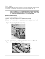
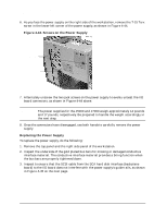
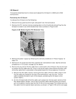
Field Replaceable Units (FRUs) FRU Removal and Replacement 6. As you face the power supply on the right side of the workstation, remove the T-15 Torx screw in the lower-left corner of the power supply, as shown in Figure 4-44. Figure 4-44. Screws on the Power Supply Jack screws T-15 Torx screw 7. Alternately unscrew the two jack screws on the power supply to evenly unseat the I/O board connectors, as shown in Figure 4-44 above. CAUTION The power supplies for the J5000 and J7000 weigh approximately 14 pounds and 17 pounds, respectively. Be prepared to handle the weight accordingly in the next step. 8. Once the connectors have disengaged, use both hands to carefully remove the power supply. Replacing the Power Supply To replace the power supply, do the following: 1. Remove the top panel and the right side panel of the workstation. 2. Inspect the underside of the gold plated bus bars for missing or damaged conductive interface material. The conductive interface material provides a biting function when the bus bars are properly tightened down. 3. Inspect to ensure that the SCSI cable from the SCA hard disk interface (backplane board) to the I/O board does not interfere with the power supply's guide rails, as shown in Figure 4-45 on the next page. 130 Chapter 4
-
 1
1 -
2
-
3
-
4
-
5
-
6
-
7
-
8
-
9
-
10
-
11
-
12
-
13
-
14
-
15
-
16
-
17
-
18
-
19
-
20
-
21
-
22
-
23
-
24
-
25
-
26
-
27
-
28
-
29
-
30
-
31
-
32
-
33
-
34
-
35
-
36
-
37
-
38
-
39
-
40
-
41
-
42
-
43
-
44
-
45
-
46
-
47
-
48
-
49
-
50
-
51
-
52
-
53
-
54
-
55
-
56
-
57
-
58
-
59
-
60
-
61
-
62
-
63
-
64
-
65
-
66
-
67
-
68
-
69
-
70
-
71
-
72
-
73
-
74
-
75
-
76
-
77
-
78
-
79
-
80
-
81
-
82
-
83
-
84
-
85
-
86
-
87
-
88
-
89
-
90
-
91
-
92
-
93
-
94
-
95
-
96
-
97
-
98
-
99
-
100
-
101
-
102
-
103
-
104
-
105
-
106
-
107
-
108
-
109
-
110
-
111
-
112
-
113
-
114
-
115
-
116
-
117
-
118
-
119
-
120
-
121
-
122
-
123
-
124
-
125
-
126
-
127
-
128
-
 129
129 -
 130
130 -
 131
131 -
 132
132 -
 133
133 -
 134
134 -
 135
135 -
 136
136 -
 137
137 -
 138
138 -
 139
139 -
140
-
141
-
142
-
143
-
144
-
145
-
146
-
147
-
148
-
149
-
150
-
151
-
152
-
153
-
154
-
155
-
156
-
157
-
158
-
159
-
160
-
161
-
162
-
163
-
164
-
165
-
166
-
167
-
168
-
169
-
170
-
171
-
172
-
173
-
174
-
175
-
176
-
177
-
178
-
179
-
180
-
181
-
182
-
183
-
184
-
185
-
186
-
187
-
188
-
189
-
190
-
191
-
192
-
193
-
194
-
195
-
196
-
197
-
198
-
199
-
200
-
201
-
202
-
203
-
204
-
205
-
206
-
207
-
208
-
209
-
210
-
211
-
212
 |
 |