HP Visualize J5000 hp Visualize J5000, J7000 workstations service handbook (a4 - Page 149
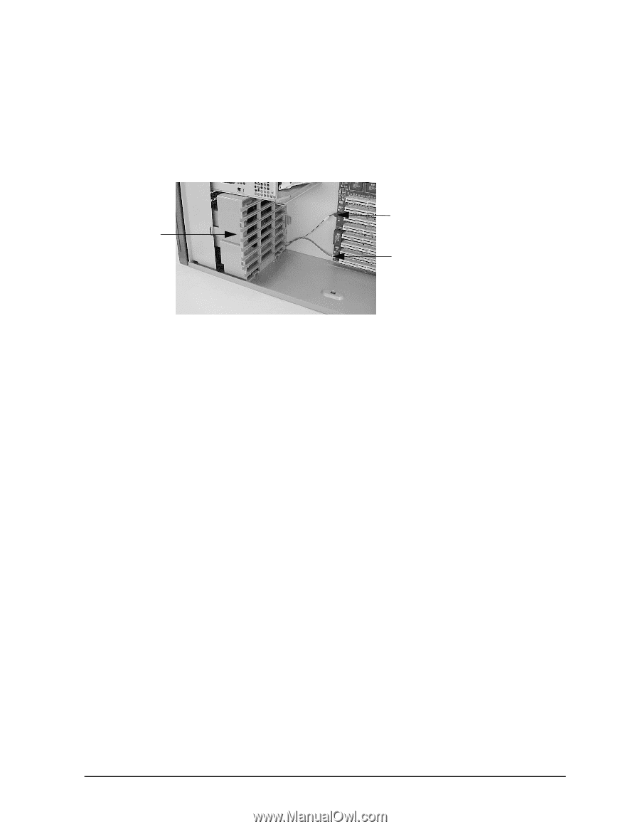
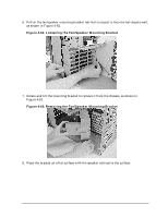
Fan/Speaker Mounting Bracket and Cables Installed
 |
View all HP Visualize J5000 manuals
Add to My Manuals
Save this manual to your list of manuals |
Page 149 highlights
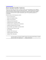
Field Replaceable Units (FRUs) FRU Removal and Replacement 3. Align the mounting bracket to snap in place over the mounting bracket's housing posts. Slide the mounting bracket along the chassis floor until it snaps into place. Take care not to pinch the cables to the inner chassis wall. Figure 4-66 shows the fan/speaker mounting bracket correctly installed. 4. Connect the fan and speaker cables to the I/O board, as shown in Figure 4-66. Figure 4-66. Fan/Speaker Mounting Bracket and Cables Installed Fan/speaker mounting bracket Fan cable Speaker cable 5. Reinstall the power supply by following the replacement procedures in "Power Supply" on page 128. 6. Reinstall the I/O cards by following the replacement procedures in "I/O Cards" on page 121. 7. Replace the PCI retainer clip. 8. Replace the top panel and the right side panel of the workstation. Chapter 4 145
-
 1
1 -
2
-
3
-
4
-
5
-
6
-
7
-
8
-
9
-
10
-
11
-
12
-
13
-
14
-
15
-
16
-
17
-
18
-
19
-
20
-
21
-
22
-
23
-
24
-
25
-
26
-
27
-
28
-
29
-
30
-
31
-
32
-
33
-
34
-
35
-
36
-
37
-
38
-
39
-
40
-
41
-
42
-
43
-
44
-
45
-
46
-
47
-
48
-
49
-
50
-
51
-
52
-
53
-
54
-
55
-
56
-
57
-
58
-
59
-
60
-
61
-
62
-
63
-
64
-
65
-
66
-
67
-
68
-
69
-
70
-
71
-
72
-
73
-
74
-
75
-
76
-
77
-
78
-
79
-
80
-
81
-
82
-
83
-
84
-
85
-
86
-
87
-
88
-
89
-
90
-
91
-
92
-
93
-
94
-
95
-
96
-
97
-
98
-
99
-
100
-
101
-
102
-
103
-
104
-
105
-
106
-
107
-
108
-
109
-
110
-
111
-
112
-
113
-
114
-
115
-
116
-
117
-
118
-
119
-
120
-
121
-
122
-
123
-
124
-
125
-
126
-
127
-
128
-
129
-
130
-
131
-
132
-
133
-
134
-
135
-
136
-
137
-
138
-
139
-
140
-
141
-
142
-
143
-
 144
144 -
 145
145 -
 146
146 -
 147
147 -
 148
148 -
 149
149 -
 150
150 -
 151
151 -
 152
152 -
 153
153 -
 154
154 -
155
-
156
-
157
-
158
-
159
-
160
-
161
-
162
-
163
-
164
-
165
-
166
-
167
-
168
-
169
-
170
-
171
-
172
-
173
-
174
-
175
-
176
-
177
-
178
-
179
-
180
-
181
-
182
-
183
-
184
-
185
-
186
-
187
-
188
-
189
-
190
-
191
-
192
-
193
-
194
-
195
-
196
-
197
-
198
-
199
-
200
-
201
-
202
-
203
-
204
-
205
-
206
-
207
-
208
-
209
-
210
-
211
-
212
 |
 |