HP Visualize J5000 hp Visualize J5000, J7000 workstations service handbook (a4 - Page 114
System Board Tray Assembly, Removing the System Board Tray Assembly
 |
View all HP Visualize J5000 manuals
Add to My Manuals
Save this manual to your list of manuals |
Page 114 highlights
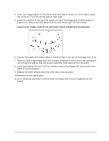
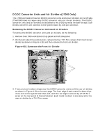
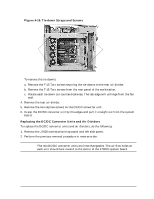
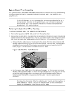
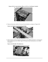
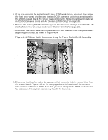
Field Replaceable Units (FRUs) FRU Removal and Replacement System Board Tray Assembly The system board in the J5000 and J7000 workstation is mounted on a tray. The following procedures describe how to remove and replace the system board tray assembly as a complete unit. NOTE If the LCD displays an error message that relates to a turbocooler fan on a microprocessor mounted on the system board, you will need to replace the entire system board tray assembly. Follow the removal and replacement procedures in this section to do so. Removing the System Board Tray Assembly To remove the system board tray assembly, do the following: 1. Remove the top panel and left side panel from the workstation. 2. Remove the one side of the flex cable that is connected to the system board. (You do not need to remove the flex cable entirely. That is, you do not need to also remove the other side of the flex cable that is connected to the I/O board for this procedure.) To do this: a. Remove the flex cable retainer covering the flex cable. (The flex cable retainer and the flex cable are located at the top of the workstation, near the rear. The flex cable straddles the center wall of the chassis, connecting the system board to the I/O board.) Figure 4-20 shows the flex cable retainer in place. Figure 4-20. The Flex Cable Retainer Flex cable retainer b. On the system board side of the flex cable, pull outward on the two outer corners of the flex cable's ejector handle. As shown in Figure 4-21 on the next page, the arrows on the flex cable indicate where you should pull on the ejector handle. (See the following CAUTION.) This disconnects the flex cable from the system board connector. CAUTION Do not pull on the center of the flex cable's ejector handle, as this may bend or break the ejector handle. Only pull on the two outer corners of the ejector handle, as indicated by the arrows on the flex cable. 110 Chapter 4
-
 1
1 -
2
-
3
-
4
-
5
-
6
-
7
-
8
-
9
-
10
-
11
-
12
-
13
-
14
-
15
-
16
-
17
-
18
-
19
-
20
-
21
-
22
-
23
-
24
-
25
-
26
-
27
-
28
-
29
-
30
-
31
-
32
-
33
-
34
-
35
-
36
-
37
-
38
-
39
-
40
-
41
-
42
-
43
-
44
-
45
-
46
-
47
-
48
-
49
-
50
-
51
-
52
-
53
-
54
-
55
-
56
-
57
-
58
-
59
-
60
-
61
-
62
-
63
-
64
-
65
-
66
-
67
-
68
-
69
-
70
-
71
-
72
-
73
-
74
-
75
-
76
-
77
-
78
-
79
-
80
-
81
-
82
-
83
-
84
-
85
-
86
-
87
-
88
-
89
-
90
-
91
-
92
-
93
-
94
-
95
-
96
-
97
-
98
-
99
-
100
-
101
-
102
-
103
-
104
-
105
-
106
-
107
-
108
-
 109
109 -
 110
110 -
 111
111 -
 112
112 -
 113
113 -
 114
114 -
 115
115 -
 116
116 -
 117
117 -
 118
118 -
 119
119 -
120
-
121
-
122
-
123
-
124
-
125
-
126
-
127
-
128
-
129
-
130
-
131
-
132
-
133
-
134
-
135
-
136
-
137
-
138
-
139
-
140
-
141
-
142
-
143
-
144
-
145
-
146
-
147
-
148
-
149
-
150
-
151
-
152
-
153
-
154
-
155
-
156
-
157
-
158
-
159
-
160
-
161
-
162
-
163
-
164
-
165
-
166
-
167
-
168
-
169
-
170
-
171
-
172
-
173
-
174
-
175
-
176
-
177
-
178
-
179
-
180
-
181
-
182
-
183
-
184
-
185
-
186
-
187
-
188
-
189
-
190
-
191
-
192
-
193
-
194
-
195
-
196
-
197
-
198
-
199
-
200
-
201
-
202
-
203
-
204
-
205
-
206
-
207
-
208
-
209
-
210
-
211
-
212
 |
 |