HP Visualize J5000 hp Visualize J5000, J7000 workstations service handbook (a4 - Page 139
Screws for the I/O Board on the Rear Panel, Replacing the I/O Board
 |
View all HP Visualize J5000 manuals
Add to My Manuals
Save this manual to your list of manuals |
Page 139 highlights
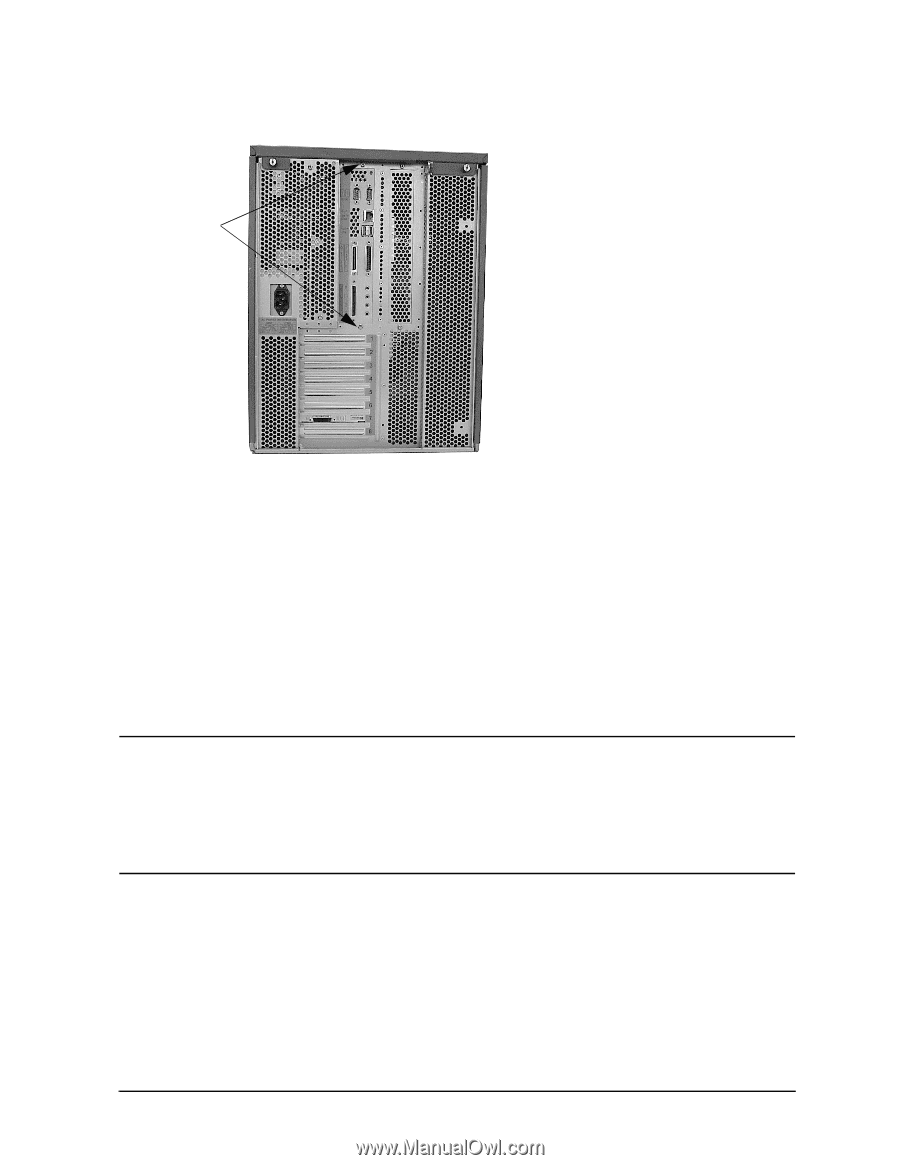
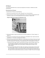
Field Replaceable Units (FRUs) FRU Removal and Replacement Figure 4-51. Screws for the I/O Board on the Rear Panel T-15 Torx screws 8. Slide the I/O board to the left, which disengages the ten keyhole standoffs holding the I/O board to the center wall of the chassis. 9. Pull the I/O board straight out until it clears the keyhole standoffs, and then lift it out of the chassis. Replacing the I/O Board To replace the I/O board, do the following: 1. Remove the top panel and the right side panel from the workstation. 2. Perform the previous removal steps in reverse. NOTE For correct installation, you must slide the I/O board to the rear of the workstation chassis until the EMI (electromagnetic interference) fingers have been compressed. During installation, it is also very easy to miss some of the keyhole standoffs that hold the I/O board to the center wall of the chassis. Therefore, be sure to verify that all ten of the keyhole standoffs are engaged with the I/O board. Chapter 4 135
-
 1
1 -
2
-
3
-
4
-
5
-
6
-
7
-
8
-
9
-
10
-
11
-
12
-
13
-
14
-
15
-
16
-
17
-
18
-
19
-
20
-
21
-
22
-
23
-
24
-
25
-
26
-
27
-
28
-
29
-
30
-
31
-
32
-
33
-
34
-
35
-
36
-
37
-
38
-
39
-
40
-
41
-
42
-
43
-
44
-
45
-
46
-
47
-
48
-
49
-
50
-
51
-
52
-
53
-
54
-
55
-
56
-
57
-
58
-
59
-
60
-
61
-
62
-
63
-
64
-
65
-
66
-
67
-
68
-
69
-
70
-
71
-
72
-
73
-
74
-
75
-
76
-
77
-
78
-
79
-
80
-
81
-
82
-
83
-
84
-
85
-
86
-
87
-
88
-
89
-
90
-
91
-
92
-
93
-
94
-
95
-
96
-
97
-
98
-
99
-
100
-
101
-
102
-
103
-
104
-
105
-
106
-
107
-
108
-
109
-
110
-
111
-
112
-
113
-
114
-
115
-
116
-
117
-
118
-
119
-
120
-
121
-
122
-
123
-
124
-
125
-
126
-
127
-
128
-
129
-
130
-
131
-
132
-
133
-
 134
134 -
 135
135 -
 136
136 -
 137
137 -
 138
138 -
 139
139 -
 140
140 -
 141
141 -
 142
142 -
 143
143 -
 144
144 -
145
-
146
-
147
-
148
-
149
-
150
-
151
-
152
-
153
-
154
-
155
-
156
-
157
-
158
-
159
-
160
-
161
-
162
-
163
-
164
-
165
-
166
-
167
-
168
-
169
-
170
-
171
-
172
-
173
-
174
-
175
-
176
-
177
-
178
-
179
-
180
-
181
-
182
-
183
-
184
-
185
-
186
-
187
-
188
-
189
-
190
-
191
-
192
-
193
-
194
-
195
-
196
-
197
-
198
-
199
-
200
-
201
-
202
-
203
-
204
-
205
-
206
-
207
-
208
-
209
-
210
-
211
-
212
 |
 |