HP Visualize J5000 hp Visualize J5000, J7000 workstations service handbook (a4 - Page 86
Overview, DC/DC Converter Units and Air Dividers J7000 Only
 |
View all HP Visualize J5000 manuals
Add to My Manuals
Save this manual to your list of manuals |
Page 86 highlights
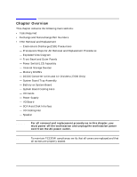
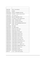
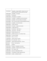
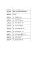
Field Replaceable Units (FRUs) Chapter Overview Chapter Overview This chapter contains the following main sections: • Tools Required • Exchange and Nonexchange Part Numbers • FRU Removal and Replacement - Electrostatic Discharge (ESD) Precautions - Prerequisite Steps for All Removal and Replacement Procedures - Exploded View Diagram - Front Bezel and Outer Panels - Power Switch/LCD Assembly - Internal Storage Devices - Memory DIMMs - DC/DC Converter Units and Air Dividers (J7000 Only) - System Board Tray Assembly - Battery on System Board - System Board Cooling Fans - I/O Cards - Power Supply - I/O Board - SCA Hard Disk Interface - I/O Cooling Fan - Speaker WARNING For all removal and replacement procedures in this chapter, you must power off the workstation and unplug the workstation power cord from the AC power outlet. NOTE To maintain FCC/EMI compliance, verify that all covers are replaced and that all screws are properly seated. 82 Chapter 4
-
 1
1 -
2
-
3
-
4
-
5
-
6
-
7
-
8
-
9
-
10
-
11
-
12
-
13
-
14
-
15
-
16
-
17
-
18
-
19
-
20
-
21
-
22
-
23
-
24
-
25
-
26
-
27
-
28
-
29
-
30
-
31
-
32
-
33
-
34
-
35
-
36
-
37
-
38
-
39
-
40
-
41
-
42
-
43
-
44
-
45
-
46
-
47
-
48
-
49
-
50
-
51
-
52
-
53
-
54
-
55
-
56
-
57
-
58
-
59
-
60
-
61
-
62
-
63
-
64
-
65
-
66
-
67
-
68
-
69
-
70
-
71
-
72
-
73
-
74
-
75
-
76
-
77
-
78
-
79
-
80
-
 81
81 -
 82
82 -
 83
83 -
 84
84 -
 85
85 -
 86
86 -
 87
87 -
 88
88 -
 89
89 -
 90
90 -
 91
91 -
92
-
93
-
94
-
95
-
96
-
97
-
98
-
99
-
100
-
101
-
102
-
103
-
104
-
105
-
106
-
107
-
108
-
109
-
110
-
111
-
112
-
113
-
114
-
115
-
116
-
117
-
118
-
119
-
120
-
121
-
122
-
123
-
124
-
125
-
126
-
127
-
128
-
129
-
130
-
131
-
132
-
133
-
134
-
135
-
136
-
137
-
138
-
139
-
140
-
141
-
142
-
143
-
144
-
145
-
146
-
147
-
148
-
149
-
150
-
151
-
152
-
153
-
154
-
155
-
156
-
157
-
158
-
159
-
160
-
161
-
162
-
163
-
164
-
165
-
166
-
167
-
168
-
169
-
170
-
171
-
172
-
173
-
174
-
175
-
176
-
177
-
178
-
179
-
180
-
181
-
182
-
183
-
184
-
185
-
186
-
187
-
188
-
189
-
190
-
191
-
192
-
193
-
194
-
195
-
196
-
197
-
198
-
199
-
200
-
201
-
202
-
203
-
204
-
205
-
206
-
207
-
208
-
209
-
210
-
211
-
212
 |
 |