HP Visualize J5000 hp Visualize J5000, J7000 workstations service handbook (a4 - Page 129
Battery on I/O Board, Removing the Battery on the I/O Board, I/O Board
 |
View all HP Visualize J5000 manuals
Add to My Manuals
Save this manual to your list of manuals |
Page 129 highlights
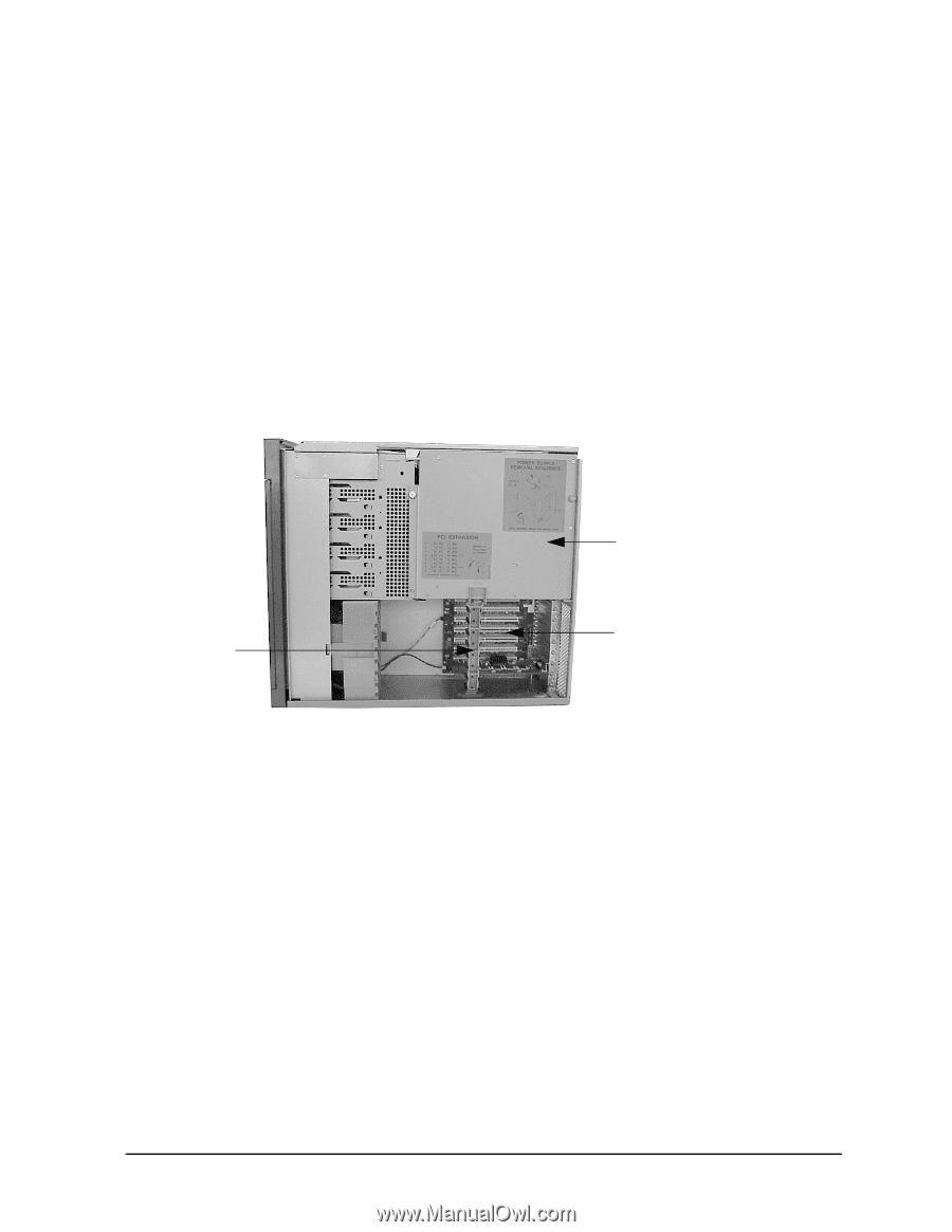
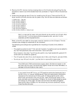
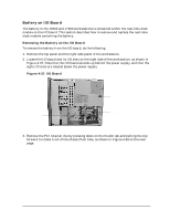
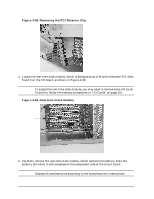
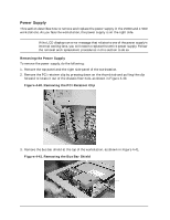
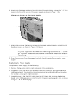
Field Replaceable Units (FRUs) FRU Removal and Replacement Battery on I/O Board The battery in the J5000 and J7000 workstations is contained within the real-time clock module on the I/O board. This section describes how to remove and replace the real-time clock module containing the battery. Removing the Battery on the I/O Board To remove the battery from the I/O board, do the following: 1. Remove the top panel and the right side panel of the workstation. 2. Locate the I/O board and its I/O slots on the right side of the workstation, as shown in Figure 4-37. Note that the I/O board extends up behind the power supply, and that the eight I/O slots are located below the power supply. Figure 4-37. I/O Board PCI retainer clip Power supply I/O board (extends up behind the power supply, above) 3. Remove the PCI retainer clip by pressing down on the thumb tab and pulling the clip forward to rotate it out of the chassis floor hole, as shown in Figure 4-38 on the next page. Chapter 4 125
-
 1
1 -
2
-
3
-
4
-
5
-
6
-
7
-
8
-
9
-
10
-
11
-
12
-
13
-
14
-
15
-
16
-
17
-
18
-
19
-
20
-
21
-
22
-
23
-
24
-
25
-
26
-
27
-
28
-
29
-
30
-
31
-
32
-
33
-
34
-
35
-
36
-
37
-
38
-
39
-
40
-
41
-
42
-
43
-
44
-
45
-
46
-
47
-
48
-
49
-
50
-
51
-
52
-
53
-
54
-
55
-
56
-
57
-
58
-
59
-
60
-
61
-
62
-
63
-
64
-
65
-
66
-
67
-
68
-
69
-
70
-
71
-
72
-
73
-
74
-
75
-
76
-
77
-
78
-
79
-
80
-
81
-
82
-
83
-
84
-
85
-
86
-
87
-
88
-
89
-
90
-
91
-
92
-
93
-
94
-
95
-
96
-
97
-
98
-
99
-
100
-
101
-
102
-
103
-
104
-
105
-
106
-
107
-
108
-
109
-
110
-
111
-
112
-
113
-
114
-
115
-
116
-
117
-
118
-
119
-
120
-
121
-
122
-
123
-
 124
124 -
 125
125 -
 126
126 -
 127
127 -
 128
128 -
 129
129 -
 130
130 -
 131
131 -
 132
132 -
 133
133 -
 134
134 -
135
-
136
-
137
-
138
-
139
-
140
-
141
-
142
-
143
-
144
-
145
-
146
-
147
-
148
-
149
-
150
-
151
-
152
-
153
-
154
-
155
-
156
-
157
-
158
-
159
-
160
-
161
-
162
-
163
-
164
-
165
-
166
-
167
-
168
-
169
-
170
-
171
-
172
-
173
-
174
-
175
-
176
-
177
-
178
-
179
-
180
-
181
-
182
-
183
-
184
-
185
-
186
-
187
-
188
-
189
-
190
-
191
-
192
-
193
-
194
-
195
-
196
-
197
-
198
-
199
-
200
-
201
-
202
-
203
-
204
-
205
-
206
-
207
-
208
-
209
-
210
-
211
-
212
 |
 |