HP Visualize J5000 hp Visualize J5000, J7000 workstations service handbook (a4 - Page 121
System Board Cooling Fans, Removing a System Board Cooling Fan
 |
View all HP Visualize J5000 manuals
Add to My Manuals
Save this manual to your list of manuals |
Page 121 highlights
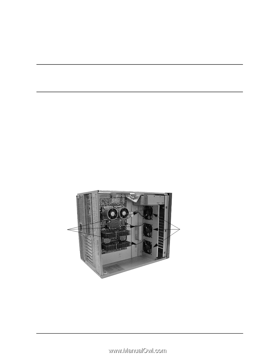
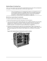
Field Replaceable Units (FRUs) FRU Removal and Replacement System Board Cooling Fans There are three system board cooling fans located behind the left side of the workstation's front panel. This section describes how to remove and replace them. NOTE If the LCD displays an error message that relates to a turbocooler fan on a microprocessor mounted on the system board, you will need to replace the entire system board tray assembly. Follow the removal and replacement procedures in "System Board Tray Assembly" on page 110. Removing a System Board Cooling Fan To remove a system board cooling fan, do the following: 1. Remove the top panel and the left side panel of the workstation. 2. If you are removing a system board cooling fan from a J7000 workstation, you must also remove the front and rear air dividers and the two DC/DC converter units that are attached to the J7000's system board. To do this, follow the removal procedures in "DC/DC Converter Units and Air Dividers (J7000 Only)" on page 108. 3. Disconnect the appropriate fan cable from the system board. Figure 4-29 shows the locations of the three system board cooling fans and their respective cables. Figure 4-30 on the next page shows the removal of a fan cable from its connector on the system board. Figure 4-29. System Board Cooling Fans and Fan Cables Fan cables System board cooling fans Chapter 4 117
-
 1
1 -
2
-
3
-
4
-
5
-
6
-
7
-
8
-
9
-
10
-
11
-
12
-
13
-
14
-
15
-
16
-
17
-
18
-
19
-
20
-
21
-
22
-
23
-
24
-
25
-
26
-
27
-
28
-
29
-
30
-
31
-
32
-
33
-
34
-
35
-
36
-
37
-
38
-
39
-
40
-
41
-
42
-
43
-
44
-
45
-
46
-
47
-
48
-
49
-
50
-
51
-
52
-
53
-
54
-
55
-
56
-
57
-
58
-
59
-
60
-
61
-
62
-
63
-
64
-
65
-
66
-
67
-
68
-
69
-
70
-
71
-
72
-
73
-
74
-
75
-
76
-
77
-
78
-
79
-
80
-
81
-
82
-
83
-
84
-
85
-
86
-
87
-
88
-
89
-
90
-
91
-
92
-
93
-
94
-
95
-
96
-
97
-
98
-
99
-
100
-
101
-
102
-
103
-
104
-
105
-
106
-
107
-
108
-
109
-
110
-
111
-
112
-
113
-
114
-
115
-
 116
116 -
 117
117 -
 118
118 -
 119
119 -
 120
120 -
 121
121 -
 122
122 -
 123
123 -
 124
124 -
 125
125 -
 126
126 -
127
-
128
-
129
-
130
-
131
-
132
-
133
-
134
-
135
-
136
-
137
-
138
-
139
-
140
-
141
-
142
-
143
-
144
-
145
-
146
-
147
-
148
-
149
-
150
-
151
-
152
-
153
-
154
-
155
-
156
-
157
-
158
-
159
-
160
-
161
-
162
-
163
-
164
-
165
-
166
-
167
-
168
-
169
-
170
-
171
-
172
-
173
-
174
-
175
-
176
-
177
-
178
-
179
-
180
-
181
-
182
-
183
-
184
-
185
-
186
-
187
-
188
-
189
-
190
-
191
-
192
-
193
-
194
-
195
-
196
-
197
-
198
-
199
-
200
-
201
-
202
-
203
-
204
-
205
-
206
-
207
-
208
-
209
-
210
-
211
-
212
 |
 |