HP Visualize J5000 hp Visualize J5000, J7000 workstations service handbook (a4 - Page 136
Bus Bar Shield Installed, T-15 Torx Screws for Securing the Power Supply
 |
View all HP Visualize J5000 manuals
Add to My Manuals
Save this manual to your list of manuals |
Page 136 highlights
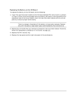
Field Replaceable Units (FRUs) FRU Removal and Replacement 7. Replace the bus bar shield by aligning the edge with the power supply edge while inserting the hooks into the slots. Rock the bus bar shield into place by pressing down towards the chassis floor. Figure 4-47 shows the bus bar shield correctly installed. Figure 4-47. Bus Bar Shield Installed 8. Insert and tighten the front, lower-left T-15 Torx screw on the power supply and the two rear panel T-15 Torx screws to secure the power supply, as shown in Figure 4-48. Figure 4-48. T-15 Torx Screws for Securing the Power Supply T-15 Torx screw T-15 Torx screws 9. Replace the PCI retainer clip. 10. Replace the top panel and the right side panel of the workstation. 132 Chapter 4
-
 1
1 -
2
-
3
-
4
-
5
-
6
-
7
-
8
-
9
-
10
-
11
-
12
-
13
-
14
-
15
-
16
-
17
-
18
-
19
-
20
-
21
-
22
-
23
-
24
-
25
-
26
-
27
-
28
-
29
-
30
-
31
-
32
-
33
-
34
-
35
-
36
-
37
-
38
-
39
-
40
-
41
-
42
-
43
-
44
-
45
-
46
-
47
-
48
-
49
-
50
-
51
-
52
-
53
-
54
-
55
-
56
-
57
-
58
-
59
-
60
-
61
-
62
-
63
-
64
-
65
-
66
-
67
-
68
-
69
-
70
-
71
-
72
-
73
-
74
-
75
-
76
-
77
-
78
-
79
-
80
-
81
-
82
-
83
-
84
-
85
-
86
-
87
-
88
-
89
-
90
-
91
-
92
-
93
-
94
-
95
-
96
-
97
-
98
-
99
-
100
-
101
-
102
-
103
-
104
-
105
-
106
-
107
-
108
-
109
-
110
-
111
-
112
-
113
-
114
-
115
-
116
-
117
-
118
-
119
-
120
-
121
-
122
-
123
-
124
-
125
-
126
-
127
-
128
-
129
-
130
-
 131
131 -
 132
132 -
 133
133 -
 134
134 -
 135
135 -
 136
136 -
 137
137 -
 138
138 -
 139
139 -
 140
140 -
 141
141 -
142
-
143
-
144
-
145
-
146
-
147
-
148
-
149
-
150
-
151
-
152
-
153
-
154
-
155
-
156
-
157
-
158
-
159
-
160
-
161
-
162
-
163
-
164
-
165
-
166
-
167
-
168
-
169
-
170
-
171
-
172
-
173
-
174
-
175
-
176
-
177
-
178
-
179
-
180
-
181
-
182
-
183
-
184
-
185
-
186
-
187
-
188
-
189
-
190
-
191
-
192
-
193
-
194
-
195
-
196
-
197
-
198
-
199
-
200
-
201
-
202
-
203
-
204
-
205
-
206
-
207
-
208
-
209
-
210
-
211
-
212
 |
 |
132
Chapter 4
Field Replaceable Units (FRUs)
FRU Removal and Replacement
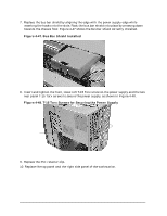
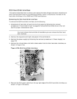
7.
Replace the bus bar shield by aligning the edge with the power supply edge while
inserting the hooks into the slots. Rock the bus bar shield into place by pressing down
towards the chassis floor. Figure 4-47 shows the bus bar shield correctly installed.
Figure 4-47. Bus Bar Shield Installed
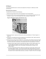
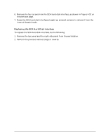
8.
Insert and tighten the front, lower-left T-15 Torx screw on the power supply and the two
rear panel T-15 Torx screws to secure the power supply, as shown in Figure 4-48.
Figure 4-48. T-15 Torx Screws for Securing the Power Supply
9.
Replace the PCI retainer clip.
10. Replace the top panel and the right side panel of the workstation.
T-15 Torx screws
T-15 Torx screw