HP Visualize J5000 hp Visualize J5000, J7000 workstations service handbook (a4 - Page 112
DC/DC Converter Units and Air Dividers J7000 Only, Removing the DC/DC Converter Units and Air Dividers
 |
View all HP Visualize J5000 manuals
Add to My Manuals
Save this manual to your list of manuals |
Page 112 highlights
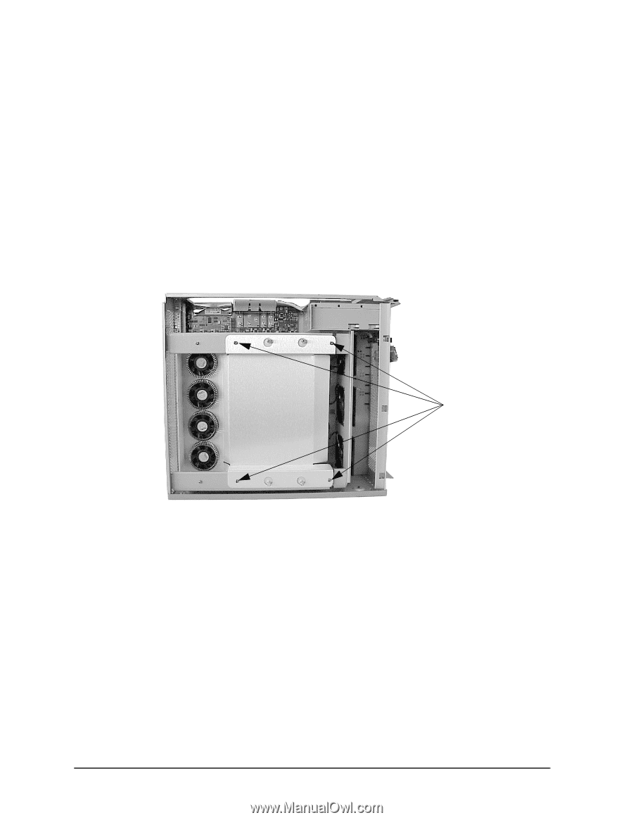
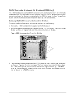
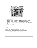
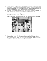
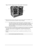
Field Replaceable Units (FRUs) FRU Removal and Replacement DC/DC Converter Units and Air Dividers (J7000 Only) The J7000 workstation has two DC/DC converter units and two air dividers on its left side. (The J5000 does not require any DC/DC converter units nor the air dividers.) The DC/DC converter units and air dividers are attached to the J7000 by metal tie-down straps. Each DC/DC converter unit connects to the system board by a 30-pin connector. Removing the DC/DC Converter Units and Air Dividers To remove the DC/DC converter units and air dividers, do the following: 1. Remove the J7000 workstation's top panel and left side panel. 2. On the left side of the workstation, remove the four T-15 Torx screws from the front air divider as shown in Figure 4-18, and then remove the front air divider. Figure 4-18. Screws on the Front Air Divider T-15 Torx screws 3. There are two tie-down straps over the DC/DC converter units and the rear air divider, as shown in Figure 4-19 on the next page. The front edge of each metal tie-down slips into a slot on the system board fan wall, and the rear edge is secured by a T-15 Torx screw on the rear panel of the workstation. Each metal tie-down is also secured to the rear air divider by a T-15 Torx screw. 108 Chapter 4
-
 1
1 -
2
-
3
-
4
-
5
-
6
-
7
-
8
-
9
-
10
-
11
-
12
-
13
-
14
-
15
-
16
-
17
-
18
-
19
-
20
-
21
-
22
-
23
-
24
-
25
-
26
-
27
-
28
-
29
-
30
-
31
-
32
-
33
-
34
-
35
-
36
-
37
-
38
-
39
-
40
-
41
-
42
-
43
-
44
-
45
-
46
-
47
-
48
-
49
-
50
-
51
-
52
-
53
-
54
-
55
-
56
-
57
-
58
-
59
-
60
-
61
-
62
-
63
-
64
-
65
-
66
-
67
-
68
-
69
-
70
-
71
-
72
-
73
-
74
-
75
-
76
-
77
-
78
-
79
-
80
-
81
-
82
-
83
-
84
-
85
-
86
-
87
-
88
-
89
-
90
-
91
-
92
-
93
-
94
-
95
-
96
-
97
-
98
-
99
-
100
-
101
-
102
-
103
-
104
-
105
-
106
-
 107
107 -
 108
108 -
 109
109 -
 110
110 -
 111
111 -
 112
112 -
 113
113 -
 114
114 -
 115
115 -
 116
116 -
 117
117 -
118
-
119
-
120
-
121
-
122
-
123
-
124
-
125
-
126
-
127
-
128
-
129
-
130
-
131
-
132
-
133
-
134
-
135
-
136
-
137
-
138
-
139
-
140
-
141
-
142
-
143
-
144
-
145
-
146
-
147
-
148
-
149
-
150
-
151
-
152
-
153
-
154
-
155
-
156
-
157
-
158
-
159
-
160
-
161
-
162
-
163
-
164
-
165
-
166
-
167
-
168
-
169
-
170
-
171
-
172
-
173
-
174
-
175
-
176
-
177
-
178
-
179
-
180
-
181
-
182
-
183
-
184
-
185
-
186
-
187
-
188
-
189
-
190
-
191
-
192
-
193
-
194
-
195
-
196
-
197
-
198
-
199
-
200
-
201
-
202
-
203
-
204
-
205
-
206
-
207
-
208
-
209
-
210
-
211
-
212
 |
 |