HP Visualize J5000 hp Visualize J5000, J7000 workstations service handbook (a4 - Page 99
Power Switch/LCD Assembly, Removing the Power Switch/LCD Assembly
 |
View all HP Visualize J5000 manuals
Add to My Manuals
Save this manual to your list of manuals |
Page 99 highlights
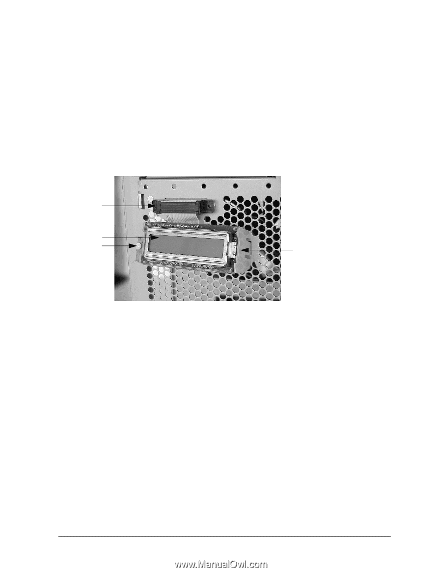
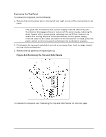
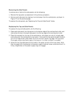
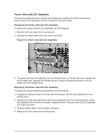
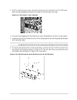
Field Replaceable Units (FRUs) FRU Removal and Replacement Power Switch/LCD Assembly This section describes how to remove and replace the J5000 and J7000 workstation's power switch/LCD assembly, which is located on the front panel. Removing the Power Switch/LCD Assembly To remove the power switch/LCD assembly, do the following: 1. Remove the front bezel of the workstation. 2. Unplug the ribbon cable from the 25-pin connector. Figure 4-5. Power Switch/LCD Assembly Ribbon cable connector LCD Power switch Release tab 3. The power switch/LCD assembly has two chassis hooks on the left side and a release tab on the right side. Squeeze the release tab and rotate the bracket outward to lift the hooks out of the chassis slots. Replacing the Power Switch/LCD Assembly To replace the power switch/LCD assembly, do the following: 1. Engage the chassis hooks on the left side of the power switch/LCD assembly into the chassis slots. 2. Squeeze the right side tab while rotating the assembly into the chassis position. When the assembly is flush with the chassis, release the tab. The power switch/LCD assembly will snap into place. 3. Plug the ribbon cable into the 25-pin connector. 4. Replace the front bezel of the workstation. Chapter 4 95
-
 1
1 -
2
-
3
-
4
-
5
-
6
-
7
-
8
-
9
-
10
-
11
-
12
-
13
-
14
-
15
-
16
-
17
-
18
-
19
-
20
-
21
-
22
-
23
-
24
-
25
-
26
-
27
-
28
-
29
-
30
-
31
-
32
-
33
-
34
-
35
-
36
-
37
-
38
-
39
-
40
-
41
-
42
-
43
-
44
-
45
-
46
-
47
-
48
-
49
-
50
-
51
-
52
-
53
-
54
-
55
-
56
-
57
-
58
-
59
-
60
-
61
-
62
-
63
-
64
-
65
-
66
-
67
-
68
-
69
-
70
-
71
-
72
-
73
-
74
-
75
-
76
-
77
-
78
-
79
-
80
-
81
-
82
-
83
-
84
-
85
-
86
-
87
-
88
-
89
-
90
-
91
-
92
-
93
-
 94
94 -
 95
95 -
 96
96 -
 97
97 -
 98
98 -
 99
99 -
 100
100 -
 101
101 -
 102
102 -
 103
103 -
 104
104 -
105
-
106
-
107
-
108
-
109
-
110
-
111
-
112
-
113
-
114
-
115
-
116
-
117
-
118
-
119
-
120
-
121
-
122
-
123
-
124
-
125
-
126
-
127
-
128
-
129
-
130
-
131
-
132
-
133
-
134
-
135
-
136
-
137
-
138
-
139
-
140
-
141
-
142
-
143
-
144
-
145
-
146
-
147
-
148
-
149
-
150
-
151
-
152
-
153
-
154
-
155
-
156
-
157
-
158
-
159
-
160
-
161
-
162
-
163
-
164
-
165
-
166
-
167
-
168
-
169
-
170
-
171
-
172
-
173
-
174
-
175
-
176
-
177
-
178
-
179
-
180
-
181
-
182
-
183
-
184
-
185
-
186
-
187
-
188
-
189
-
190
-
191
-
192
-
193
-
194
-
195
-
196
-
197
-
198
-
199
-
200
-
201
-
202
-
203
-
204
-
205
-
206
-
207
-
208
-
209
-
210
-
211
-
212
 |
 |