HP Visualize J5000 hp Visualize J5000, J7000 workstations service handbook (a4 - Page 117
Fan Cable Connector Tabs and Rear Panel Screws, in the next two steps.
 |
View all HP Visualize J5000 manuals
Add to My Manuals
Save this manual to your list of manuals |
Page 117 highlights
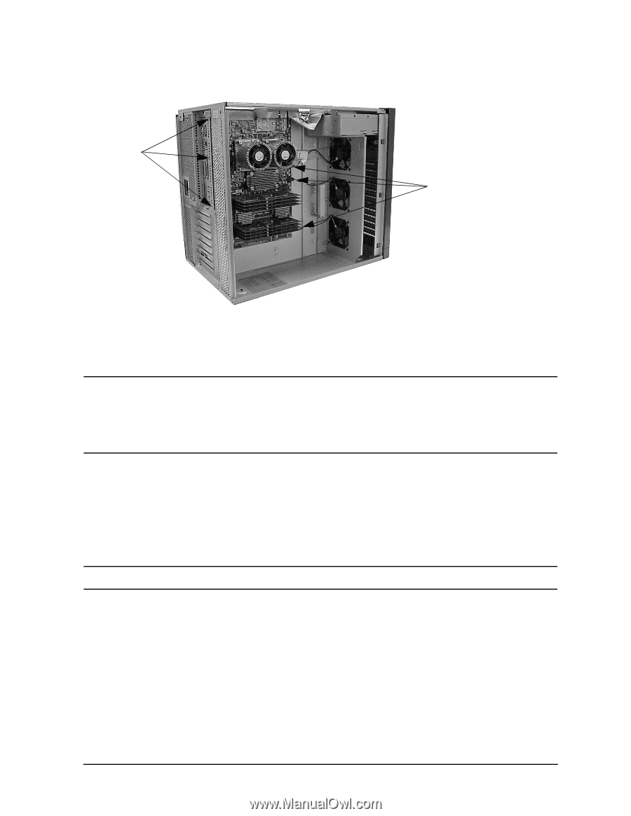
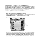
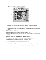
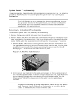
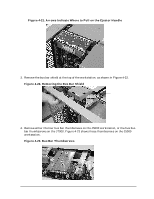
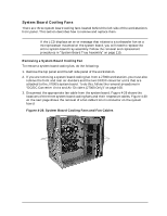
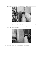
Field Replaceable Units (FRUs) FRU Removal and Replacement Figure 4-25. Fan Cable Connector Tabs and Rear Panel Screws T-15 Torx screws on rear panel Connector tabs for the 3 fan cables 9. Remove the three T-15 Torx screws that secure the system board tray assembly to the rear panel of the workstation, as shown in Figure 4-25 above. CAUTION The J7000 workstation's system board has four turbocoolers mounted vertically to the left edge. Thus, the complete system board tray assembly will be heavily weighted to one side. Approximate total weight for the system board tray assembly is 12 lbs. Be prepared to handle the weight accordingly in the next two steps. 10.Grasp the handle on the system board tray assembly and firmly slide the tray assembly to the right, toward the front of the workstation. The sheet metal hooks on the workstation's center wall will disengage from the holes on the system board tray assembly. 11.Support the left side of the system board tray assembly and carefully pull the tray outward. NOTE Do not remove the system board from the tray. Chapter 4 113
-
 1
1 -
2
-
3
-
4
-
5
-
6
-
7
-
8
-
9
-
10
-
11
-
12
-
13
-
14
-
15
-
16
-
17
-
18
-
19
-
20
-
21
-
22
-
23
-
24
-
25
-
26
-
27
-
28
-
29
-
30
-
31
-
32
-
33
-
34
-
35
-
36
-
37
-
38
-
39
-
40
-
41
-
42
-
43
-
44
-
45
-
46
-
47
-
48
-
49
-
50
-
51
-
52
-
53
-
54
-
55
-
56
-
57
-
58
-
59
-
60
-
61
-
62
-
63
-
64
-
65
-
66
-
67
-
68
-
69
-
70
-
71
-
72
-
73
-
74
-
75
-
76
-
77
-
78
-
79
-
80
-
81
-
82
-
83
-
84
-
85
-
86
-
87
-
88
-
89
-
90
-
91
-
92
-
93
-
94
-
95
-
96
-
97
-
98
-
99
-
100
-
101
-
102
-
103
-
104
-
105
-
106
-
107
-
108
-
109
-
110
-
111
-
 112
112 -
 113
113 -
 114
114 -
 115
115 -
 116
116 -
 117
117 -
 118
118 -
 119
119 -
 120
120 -
 121
121 -
 122
122 -
123
-
124
-
125
-
126
-
127
-
128
-
129
-
130
-
131
-
132
-
133
-
134
-
135
-
136
-
137
-
138
-
139
-
140
-
141
-
142
-
143
-
144
-
145
-
146
-
147
-
148
-
149
-
150
-
151
-
152
-
153
-
154
-
155
-
156
-
157
-
158
-
159
-
160
-
161
-
162
-
163
-
164
-
165
-
166
-
167
-
168
-
169
-
170
-
171
-
172
-
173
-
174
-
175
-
176
-
177
-
178
-
179
-
180
-
181
-
182
-
183
-
184
-
185
-
186
-
187
-
188
-
189
-
190
-
191
-
192
-
193
-
194
-
195
-
196
-
197
-
198
-
199
-
200
-
201
-
202
-
203
-
204
-
205
-
206
-
207
-
208
-
209
-
210
-
211
-
212
 |
 |