HP Visualize J5000 hp Visualize J5000, J7000 workstations service handbook (a4 - Page 30
LAN 10/100 BaseT RJ45 Connector, USB Connectors, Parallel Connector
 |
View all HP Visualize J5000 manuals
Add to My Manuals
Save this manual to your list of manuals |
Page 30 highlights
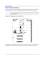
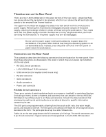
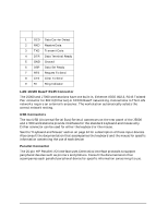
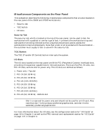
Product Information Rear Panel Components Table 1-4. Serial I/O Pins Pin No. Signal Description 1 DCD Data Carrier Detect 2 RXD Receive Data 3 TXD Transmit Data 4 DTR Data Terminal Ready 5 GND Ground 6 DSR Data Set Ready 7 RTS Request To Send 8 CTS Clear To Send 9 RI Ring Indicator LAN 10/100 BaseT RJ45 Connector The J5000 and J7000 workstations have one built-in, Ethernet IEEE 802.3, RJ45 Twisted Pair connector for 802.3 (Ethernet) or 10/100 BaseT networking. Connections to ThinLAN networks require an external transceiver. The workstation automatically selects the correct network setting. USB Connectors The two USB (Universal Serial Bus) Series A connectors on the rear panel of the J5000 and J7000 workstations provide interfaces for the standard keyboard and mouse only. Either connector can be used for either the keyboard or the mouse. See the "Keyboard and Mouse" section on page 34 for a description of these input devices. Also consult the documentation that accompanies the keyboard and the mouse for specific information concerning the use of each device. Parallel Connector The 25-pin HP Parallel I/O interface uses Centronics interface protocols to support peripheral devices such as printers and plotters. Consult the documentation that accompanies each parallel peripheral device for specific information concerning its use. 26 Chapter 1
-
 1
1 -
2
-
3
-
4
-
5
-
6
-
7
-
8
-
9
-
10
-
11
-
12
-
13
-
14
-
15
-
16
-
17
-
18
-
19
-
20
-
21
-
22
-
23
-
24
-
 25
25 -
 26
26 -
 27
27 -
 28
28 -
 29
29 -
 30
30 -
 31
31 -
 32
32 -
 33
33 -
 34
34 -
 35
35 -
36
-
37
-
38
-
39
-
40
-
41
-
42
-
43
-
44
-
45
-
46
-
47
-
48
-
49
-
50
-
51
-
52
-
53
-
54
-
55
-
56
-
57
-
58
-
59
-
60
-
61
-
62
-
63
-
64
-
65
-
66
-
67
-
68
-
69
-
70
-
71
-
72
-
73
-
74
-
75
-
76
-
77
-
78
-
79
-
80
-
81
-
82
-
83
-
84
-
85
-
86
-
87
-
88
-
89
-
90
-
91
-
92
-
93
-
94
-
95
-
96
-
97
-
98
-
99
-
100
-
101
-
102
-
103
-
104
-
105
-
106
-
107
-
108
-
109
-
110
-
111
-
112
-
113
-
114
-
115
-
116
-
117
-
118
-
119
-
120
-
121
-
122
-
123
-
124
-
125
-
126
-
127
-
128
-
129
-
130
-
131
-
132
-
133
-
134
-
135
-
136
-
137
-
138
-
139
-
140
-
141
-
142
-
143
-
144
-
145
-
146
-
147
-
148
-
149
-
150
-
151
-
152
-
153
-
154
-
155
-
156
-
157
-
158
-
159
-
160
-
161
-
162
-
163
-
164
-
165
-
166
-
167
-
168
-
169
-
170
-
171
-
172
-
173
-
174
-
175
-
176
-
177
-
178
-
179
-
180
-
181
-
182
-
183
-
184
-
185
-
186
-
187
-
188
-
189
-
190
-
191
-
192
-
193
-
194
-
195
-
196
-
197
-
198
-
199
-
200
-
201
-
202
-
203
-
204
-
205
-
206
-
207
-
208
-
209
-
210
-
211
-
212
 |
 |