HP Visualize J5000 hp Visualize J5000, J7000 workstations service handbook (a4 - Page 29
Thumbscrews on the Rear Panel, Connectors on the Rear Panel, RS-232C Serial Connectors
 |
View all HP Visualize J5000 manuals
Add to My Manuals
Save this manual to your list of manuals |
Page 29 highlights
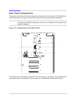
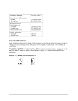
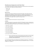
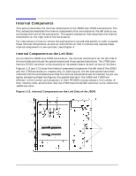
Product Information Rear Panel Components Thumbscrews on the Rear Panel There are two T-15 thumbscrews in the upper corners of the rear panel. Loosening these two screws allows the top panel to be removed, which in turn allows the left and right side panels to be removed from the workstation. The upper-left thumbscrew engages the safety interlock switch with the workstation's power supply. Removing this thumbscrew disengages all power outputs of the power supply, reducing the danger of electric shock while servicing the workstation. Thus, make sure that this power supply interlock thumbscrew is firmly retightened when you finish servicing the workstation, or the power supply may still be disengaged. CAUTION Do not use the power supply interlock thumbscrew to power down the workstation. This power down method may hang the operating system in an unrecoverable state. Instead, press the power switch on the front panel to power down the workstation. Connectors on the Rear Panel This subsection describes the following connectors that are located on the rear panel. Note that these connectors are discussed in the order in which they are located, top to bottom, on the rear panel. • RS-232C Serial connectors • LAN 10/100 BaseT RJ45 connector • USB connectors (for keyboard and mouse only) • Parallel connector • SCSI connectors • Audio connectors • Power cord connector RS-232C Serial Connectors There are a variety of pointing devices (such as a mouse or trackball) or peripheral devices (including printers, plotters, modems, and scanners) that can attach to the two RS-232C SIO (Serial Input/Output) ports on these workstations. Consult the documentation that accompanies each serial pointing device or peripheral device for specific information concerning its use. The SIO ports are programmable, allowing functions such as bit rate, character length, parity, and stop bits to be set. The SIO ports are used as interfaces for serial asynchronous devices to the CPU. The ports operate at up to a 115.2 Kbaud rate. Table 1-4 on the next page shows the SIO connector pin listings. The serial connectors are 9-pin D-sub connectors. Signal names are those specified in the EIA RS-232 standard. Chapter 1 25
-
 1
1 -
2
-
3
-
4
-
5
-
6
-
7
-
8
-
9
-
10
-
11
-
12
-
13
-
14
-
15
-
16
-
17
-
18
-
19
-
20
-
21
-
22
-
23
-
 24
24 -
 25
25 -
 26
26 -
 27
27 -
 28
28 -
 29
29 -
 30
30 -
 31
31 -
 32
32 -
 33
33 -
 34
34 -
35
-
36
-
37
-
38
-
39
-
40
-
41
-
42
-
43
-
44
-
45
-
46
-
47
-
48
-
49
-
50
-
51
-
52
-
53
-
54
-
55
-
56
-
57
-
58
-
59
-
60
-
61
-
62
-
63
-
64
-
65
-
66
-
67
-
68
-
69
-
70
-
71
-
72
-
73
-
74
-
75
-
76
-
77
-
78
-
79
-
80
-
81
-
82
-
83
-
84
-
85
-
86
-
87
-
88
-
89
-
90
-
91
-
92
-
93
-
94
-
95
-
96
-
97
-
98
-
99
-
100
-
101
-
102
-
103
-
104
-
105
-
106
-
107
-
108
-
109
-
110
-
111
-
112
-
113
-
114
-
115
-
116
-
117
-
118
-
119
-
120
-
121
-
122
-
123
-
124
-
125
-
126
-
127
-
128
-
129
-
130
-
131
-
132
-
133
-
134
-
135
-
136
-
137
-
138
-
139
-
140
-
141
-
142
-
143
-
144
-
145
-
146
-
147
-
148
-
149
-
150
-
151
-
152
-
153
-
154
-
155
-
156
-
157
-
158
-
159
-
160
-
161
-
162
-
163
-
164
-
165
-
166
-
167
-
168
-
169
-
170
-
171
-
172
-
173
-
174
-
175
-
176
-
177
-
178
-
179
-
180
-
181
-
182
-
183
-
184
-
185
-
186
-
187
-
188
-
189
-
190
-
191
-
192
-
193
-
194
-
195
-
196
-
197
-
198
-
199
-
200
-
201
-
202
-
203
-
204
-
205
-
206
-
207
-
208
-
209
-
210
-
211
-
212
 |
 |