D-Link DWC-1000 User Manual - Page 149
Channel Plan History
 |
View all D-Link DWC-1000 manuals
Add to My Manuals
Save this manual to your list of manuals |
Page 149 highlights
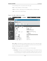
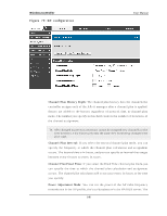
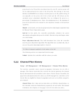
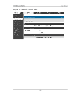
Wireless Controller User Manual power level in the AP profile is the default level for the AP, and the power will not be adjus ted below the value in the AP profile. The s ettings in the local database and RADIUS s erver always override power s et in the profile s etting. If y o u man u ally s et t h e p o wer, t h e lev el is fixed an d t h e A P will n o t u s e t h e au t o mat ic p o wer ad ju s t men t alg o rit h m. Yo u can co n fig u re t h e p o wer as a p ercen t ag e o f maximu m p o wer, wh ere t h e maximu m p o wer is t h e min imu m o f p o wer lev el allo wed fo r t h e ch an n el b y t h e reg u lat o ry d o main o r t h e h ard ware c a p a b ilit y . Manual : In t h is mo d e, y o u ru n t h e p rop os ed p o wer ad ju s t men t s man u ally fro m t h e M an u al Po wer A d ju s t men t s p ag e. Interval : In t h is mo d e, t h e co n t ro ller p erio d ically calcu lat es t h e p o wer ad ju s t men ts an d ap p lies t he p o wer fo r all A Ps . Th e in t erv al p erio d b eg in s wh en y o u click Su b mit . Power Adjus tment Interval : Th is field d et ermin es h o w o ft en t h e co n t ro ller ru n s t h e p o wer ad just men t alg o rit h m. Th e alg o rit h m ru n s au t o mat ically o n ly if y o u s et t h e p o wer ad ju s t men t mo d e t o In t erv al. This s etting gets applied to both radios of the AP. The following actions are s upported from this page: S ubmi t: Up d at es t h e co n t ro ller wit h t h e v alu es y o u en t er. 5.2.2 Channel Plan History Setup > AP Management > RF Management > Channel Plan History Th e wireles s co n t ro ller s t o res ch an n el as s ig n men t in fo rmat io n fo r t h e A Ps it man ag es . Th e Clu s t er Co n t ro ller t h at co n t ro ls t h e clu s t er main t ain s t h e ch an n el h is t o ry in fo rmat io n fo r all co n t ro llers in t h e clu s t er. On t h e Clu s t er Co n t ro ller, t h e p ag e s h ows in fo rmat io n ab out t h e rad io s o n all A Ps man ag ed b y co n t ro lle rs in t h e clu s t er t h at are elig ib le fo r ch an n el as s ig n men t an d were s u cces s fu lly as s ig n ed a new channel. Channel Pl an: Th e 5 GHz an d 2.4 GHz rad io s u s e d ifferen t ch an n el p lan s , s o the controller tracks the channel his tory s eparately for each radio. The channel in fo rmat io n t h at d is p lay s o n t h e p ag e is o n ly fo r t h e rad io y o u s elect . 147
-
 1
1 -
2
-
3
-
4
-
5
-
6
-
7
-
8
-
9
-
10
-
11
-
12
-
13
-
14
-
15
-
16
-
17
-
18
-
19
-
20
-
21
-
22
-
23
-
24
-
25
-
26
-
27
-
28
-
29
-
30
-
31
-
32
-
33
-
34
-
35
-
36
-
37
-
38
-
39
-
40
-
41
-
42
-
43
-
44
-
45
-
46
-
47
-
48
-
49
-
50
-
51
-
52
-
53
-
54
-
55
-
56
-
57
-
58
-
59
-
60
-
61
-
62
-
63
-
64
-
65
-
66
-
67
-
68
-
69
-
70
-
71
-
72
-
73
-
74
-
75
-
76
-
77
-
78
-
79
-
80
-
81
-
82
-
83
-
84
-
85
-
86
-
87
-
88
-
89
-
90
-
91
-
92
-
93
-
94
-
95
-
96
-
97
-
98
-
99
-
100
-
101
-
102
-
103
-
104
-
105
-
106
-
107
-
108
-
109
-
110
-
111
-
112
-
113
-
114
-
115
-
116
-
117
-
118
-
119
-
120
-
121
-
122
-
123
-
124
-
125
-
126
-
127
-
128
-
129
-
130
-
131
-
132
-
133
-
134
-
135
-
136
-
137
-
138
-
139
-
140
-
141
-
142
-
143
-
 144
144 -
 145
145 -
 146
146 -
 147
147 -
 148
148 -
 149
149 -
 150
150 -
 151
151 -
 152
152 -
 153
153 -
 154
154 -
155
-
156
-
157
-
158
-
159
-
160
-
161
-
162
-
163
-
164
-
165
-
166
-
167
-
168
-
169
-
170
-
171
-
172
-
173
-
174
-
175
-
176
-
177
-
178
-
179
-
180
-
181
-
182
-
183
-
184
-
185
-
186
-
187
-
188
-
189
-
190
-
191
-
192
-
193
-
194
-
195
-
196
-
197
-
198
-
199
-
200
-
201
-
202
-
203
-
204
-
205
-
206
-
207
-
208
-
209
-
210
-
211
-
212
-
213
-
214
-
215
-
216
-
217
-
218
-
219
-
220
-
221
-
222
-
223
-
224
-
225
-
226
-
227
-
228
-
229
-
230
-
231
-
232
-
233
-
234
-
235
-
236
-
237
-
238
-
239
-
240
-
241
-
242
-
243
-
244
-
245
-
246
-
247
-
248
-
249
-
250
-
251
-
252
-
253
-
254
-
255
-
256
-
257
-
258
-
259
-
260
-
261
-
262
-
263
-
264
-
265
-
266
-
267
-
268
-
269
-
270
-
271
-
272
-
273
-
274
-
275
-
276
-
277
-
278
-
279
-
280
-
281
-
282
-
283
-
284
-
285
-
286
-
287
-
288
-
289
-
290
-
291
-
292
-
293
-
294
-
295
-
296
-
297
-
298
-
299
-
300
-
301
-
302
-
303
-
304
-
305
-
306
-
307
-
308
-
309
-
310
-
311
-
312
-
313
-
314
-
315
-
316
-
317
-
318
-
319
-
320
-
321
-
322
-
323
-
324
 |
 |