D-Link DWC-1000 User Manual - Page 178
Load Balancing
 |
View all D-Link DWC-1000 manuals
Add to My Manuals
Save this manual to your list of manuals |
Page 178 highlights
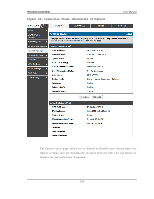
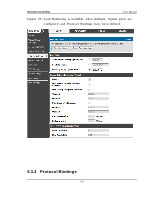
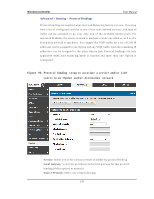
Wireless Controller User Manual DNS l ook up us i ng Opti on S ervers : DNS Lo o ku p o f t h e cu s t o m DNS Serv ers can b e s p ecified t o ch eck t h e co n n ect iv it y o f t h e p rimary lin k. Pi ng thes e IP addres s es : Th es e IP's will b e p in g ed at reg u lar in t erv als t o check the connectivity of the primary link. Retry Interval i s : Th e n u mb er t ells t h e co n t ro ller h o w o ft en it s h o u ld ru n t h e ab o v e co n fig u red failu re d et ect io n met h o d . Fai l over after : Th is s et s t h e n u mb er o f ret ries aft er wh ich failo v er is in it ia t e d . 6.3.2 Load Balancing Th is feat u re allo ws y o u t o u s e mu lt ip le Op t io n lin ks (an d p res u mab ly mu lt ip le ISP‟s ) s imu lt an eo u s ly . A ft er co n fig u rin g mo re t h an o n e Op t io n p o rt , t h e lo ad b alan cin g o p t io n is av ailab le t o carry t raffic o v er mo re t h an o n e lin k. Pro t o co l bindings are us ed to s egregate and assign s e rvices over one Option port in order to man ag e in t ern et flo w. Th e co n fig u red failu re d et ect io n met h o d is u s ed at reg u lar in t erv als o n all co n fig u red Op t io n p o rt s wh en in Lo ad Balan cin g mo d e. DW C-1000 cu rren t ly s u p p o rt s t h ree alg o rit h ms fo r Lo ad Balan cin g : Round Robi n: Th is alg o rit h m is p art icu larly u s efu l wh en t h e co n n ect io n s p eed o f one Option port greatly differs from another. In this cas e you can define protocol b in d in g s t o ro u t e lo w-lat en cy s erv ices (s u ch as VOIP) o v er t h e h ig h er -s p eed lin k an d let lo w-v o lu me b ackg ro u nd t raffic (s u ch as SM TP) g o o v er t h e lo wer s p eed lin k. Pro t o co l b in d in g is exp lain ed in n ext s ect io n . S pi l l Over : If Sp ill Ov er met h o d is s elect ed , Op t io n 1act s as a d ed icat ed lin k t ill a t h res h old is reached. A ft er t h is, Op t io n 2 will b e u s ed fo r n ew co n n ectio ns. Yo u can co n fig u re s p ill-o v er mo d e b y u s in g fo llo in g o p t io n s : Load Tolerance: It is the percentage of bandwidth after which the controller controllers to s econdary Option. Max B andwi dth: Th is s et s t h e maximu m b an d wid t h t o lerab le b y t h e p rimary Op t io n . If t h e lin k b an d wid t h g o es ab o v e t h e lo ad t o leran ce v alu e o f max b an d wid t h , t h e co n t ro ller will s p ill-o v er t h e n ext co n n ect io n s t o s eco n d ary Op t io n . 176
-
 1
1 -
2
-
3
-
4
-
5
-
6
-
7
-
8
-
9
-
10
-
11
-
12
-
13
-
14
-
15
-
16
-
17
-
18
-
19
-
20
-
21
-
22
-
23
-
24
-
25
-
26
-
27
-
28
-
29
-
30
-
31
-
32
-
33
-
34
-
35
-
36
-
37
-
38
-
39
-
40
-
41
-
42
-
43
-
44
-
45
-
46
-
47
-
48
-
49
-
50
-
51
-
52
-
53
-
54
-
55
-
56
-
57
-
58
-
59
-
60
-
61
-
62
-
63
-
64
-
65
-
66
-
67
-
68
-
69
-
70
-
71
-
72
-
73
-
74
-
75
-
76
-
77
-
78
-
79
-
80
-
81
-
82
-
83
-
84
-
85
-
86
-
87
-
88
-
89
-
90
-
91
-
92
-
93
-
94
-
95
-
96
-
97
-
98
-
99
-
100
-
101
-
102
-
103
-
104
-
105
-
106
-
107
-
108
-
109
-
110
-
111
-
112
-
113
-
114
-
115
-
116
-
117
-
118
-
119
-
120
-
121
-
122
-
123
-
124
-
125
-
126
-
127
-
128
-
129
-
130
-
131
-
132
-
133
-
134
-
135
-
136
-
137
-
138
-
139
-
140
-
141
-
142
-
143
-
144
-
145
-
146
-
147
-
148
-
149
-
150
-
151
-
152
-
153
-
154
-
155
-
156
-
157
-
158
-
159
-
160
-
161
-
162
-
163
-
164
-
165
-
166
-
167
-
168
-
169
-
170
-
171
-
172
-
 173
173 -
 174
174 -
 175
175 -
 176
176 -
 177
177 -
 178
178 -
 179
179 -
 180
180 -
 181
181 -
 182
182 -
 183
183 -
184
-
185
-
186
-
187
-
188
-
189
-
190
-
191
-
192
-
193
-
194
-
195
-
196
-
197
-
198
-
199
-
200
-
201
-
202
-
203
-
204
-
205
-
206
-
207
-
208
-
209
-
210
-
211
-
212
-
213
-
214
-
215
-
216
-
217
-
218
-
219
-
220
-
221
-
222
-
223
-
224
-
225
-
226
-
227
-
228
-
229
-
230
-
231
-
232
-
233
-
234
-
235
-
236
-
237
-
238
-
239
-
240
-
241
-
242
-
243
-
244
-
245
-
246
-
247
-
248
-
249
-
250
-
251
-
252
-
253
-
254
-
255
-
256
-
257
-
258
-
259
-
260
-
261
-
262
-
263
-
264
-
265
-
266
-
267
-
268
-
269
-
270
-
271
-
272
-
273
-
274
-
275
-
276
-
277
-
278
-
279
-
280
-
281
-
282
-
283
-
284
-
285
-
286
-
287
-
288
-
289
-
290
-
291
-
292
-
293
-
294
-
295
-
296
-
297
-
298
-
299
-
300
-
301
-
302
-
303
-
304
-
305
-
306
-
307
-
308
-
309
-
310
-
311
-
312
-
313
-
314
-
315
-
316
-
317
-
318
-
319
-
320
-
321
-
322
-
323
-
324
 |
 |