D-Link DWC-1000 User Manual - Page 189
OSPFv2 Configuration
 |
View all D-Link DWC-1000 manuals
Add to My Manuals
Save this manual to your list of manuals |
Page 189 highlights
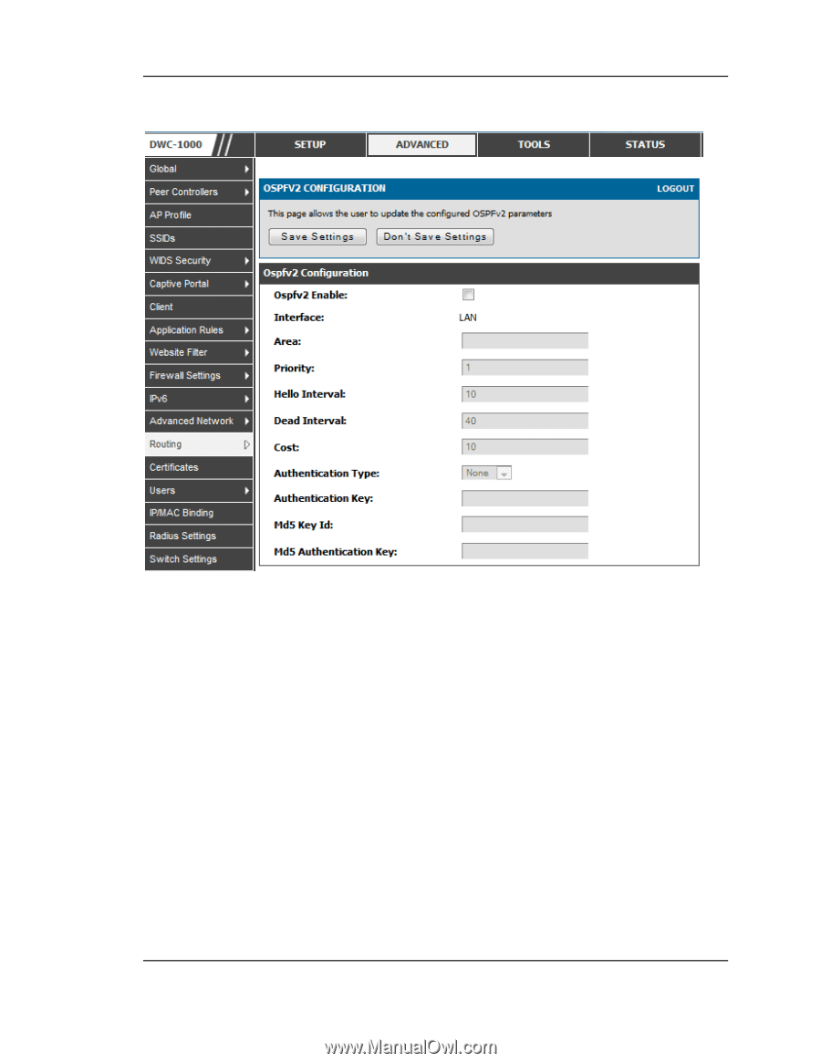
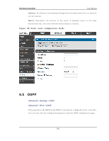
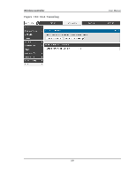
Wireless Controller Figure 101 : OSPFv2 Configuratio n User Manual OS PFv2 Enabl e : A ch eck b o x t o en ab le/ d is ab le OSPFv 2. Interface : Th e p h y s ical n et wo rk in t erface o n wh ich OSPFv 2 is En ab led / Dis ab led . Area: Th e area t o wh ich t h e in t erface b elo n g s .En t er v alu es fro m 1 t o 255 .Two ro u t ers h avin g a co mmo n s eg men t; t h eir in t erfaces h av e t o b elo n g t o t h e s ame area o n t h at s egmen t. Th e in t erfaces s hou ld b elo n g t o t h e s ame s u b n et an d h av e s imilar mas k. Pri ori ty:Help s t o d etermin e t h e OSPFv 2 d es ign at ed ro ut er fo r a n et wo rk.Th e ro u t er wit h t h e h ig h es t p rio rit y will b e mo re elig ib le t o b eco me Des ig n ated Ro u t er. Set t in g t h e v alu e t o 0, makes t h e ro u t er in elig ib le t o b eco me Des ig nated Ro u t er. Th e d efault v alu e is 1.Lo wer v alu e mean s h ig h er p rio rit y . Hel l oInterval :Th e n u mb er o f s eco n d s fo r Hello In t erv al t imer v alu e. Set t in g t h is v alu e, Hello p acket will b e s en t ev ery t imer v alu e s eco nds o n t he s pecified in t erface. 187
-
 1
1 -
2
-
3
-
4
-
5
-
6
-
7
-
8
-
9
-
10
-
11
-
12
-
13
-
14
-
15
-
16
-
17
-
18
-
19
-
20
-
21
-
22
-
23
-
24
-
25
-
26
-
27
-
28
-
29
-
30
-
31
-
32
-
33
-
34
-
35
-
36
-
37
-
38
-
39
-
40
-
41
-
42
-
43
-
44
-
45
-
46
-
47
-
48
-
49
-
50
-
51
-
52
-
53
-
54
-
55
-
56
-
57
-
58
-
59
-
60
-
61
-
62
-
63
-
64
-
65
-
66
-
67
-
68
-
69
-
70
-
71
-
72
-
73
-
74
-
75
-
76
-
77
-
78
-
79
-
80
-
81
-
82
-
83
-
84
-
85
-
86
-
87
-
88
-
89
-
90
-
91
-
92
-
93
-
94
-
95
-
96
-
97
-
98
-
99
-
100
-
101
-
102
-
103
-
104
-
105
-
106
-
107
-
108
-
109
-
110
-
111
-
112
-
113
-
114
-
115
-
116
-
117
-
118
-
119
-
120
-
121
-
122
-
123
-
124
-
125
-
126
-
127
-
128
-
129
-
130
-
131
-
132
-
133
-
134
-
135
-
136
-
137
-
138
-
139
-
140
-
141
-
142
-
143
-
144
-
145
-
146
-
147
-
148
-
149
-
150
-
151
-
152
-
153
-
154
-
155
-
156
-
157
-
158
-
159
-
160
-
161
-
162
-
163
-
164
-
165
-
166
-
167
-
168
-
169
-
170
-
171
-
172
-
173
-
174
-
175
-
176
-
177
-
178
-
179
-
180
-
181
-
182
-
183
-
 184
184 -
 185
185 -
 186
186 -
 187
187 -
 188
188 -
 189
189 -
 190
190 -
 191
191 -
 192
192 -
 193
193 -
 194
194 -
195
-
196
-
197
-
198
-
199
-
200
-
201
-
202
-
203
-
204
-
205
-
206
-
207
-
208
-
209
-
210
-
211
-
212
-
213
-
214
-
215
-
216
-
217
-
218
-
219
-
220
-
221
-
222
-
223
-
224
-
225
-
226
-
227
-
228
-
229
-
230
-
231
-
232
-
233
-
234
-
235
-
236
-
237
-
238
-
239
-
240
-
241
-
242
-
243
-
244
-
245
-
246
-
247
-
248
-
249
-
250
-
251
-
252
-
253
-
254
-
255
-
256
-
257
-
258
-
259
-
260
-
261
-
262
-
263
-
264
-
265
-
266
-
267
-
268
-
269
-
270
-
271
-
272
-
273
-
274
-
275
-
276
-
277
-
278
-
279
-
280
-
281
-
282
-
283
-
284
-
285
-
286
-
287
-
288
-
289
-
290
-
291
-
292
-
293
-
294
-
295
-
296
-
297
-
298
-
299
-
300
-
301
-
302
-
303
-
304
-
305
-
306
-
307
-
308
-
309
-
310
-
311
-
312
-
313
-
314
-
315
-
316
-
317
-
318
-
319
-
320
-
321
-
322
-
323
-
324
 |
 |